An elastic shielding ring for signal transmission

A technology of signal transmission and shielding ring, which is applied in the direction of protective grounding/shielding device of connecting parts, parts of connecting device, coupling device, etc., which can solve the problem of reducing the connection efficiency of PCB board and unsolved the problem of PCB board and PCB board tolerance. Grounding tolerance problems, restricting the application effect of PCB boards, etc., to achieve the effect of solving tolerance

Active Publication Date: 2019-01-04
SHANGHAI AEROSPACE SCI & IND ELECTRIC APPLIANCE RES INST
View PDF9 Cites 3 Cited by
  • Summary
  • Abstract
  • Description
  • Claims
  • Application Information

AI Technical Summary

Problems solved by technology

In order to realize the tolerance design, the selected contact form has the following characteristics: a. Use sockets or plugs at both ends, and the connection mode through the middle transfer, which is composed of three components; b. Use sockets or plugs at both ends, through welding The existing problem is that the above-mentioned structures are all in axial rigid contact, which cannot meet the requirements for radial tolerance when the PCB board is connected to the PCB board, which reduces the connection efficiency of the PCB board and restricts the PCB board. The application effect of the board
The above structure only solves the tolerance problem of the axial elastic connection between the PCB board and the PCB board, and does not solve the tolerance problem of the radial connection between the PCB board and the PCB board, that is, the tolerance problem of the shell grounding

Method used


Image

  • An elastic shielding ring for signal transmission
  • An elastic shielding ring for signal transmission
  • An elastic shielding ring for signal transmission

Examples


Embodiment 1

[0033] The structure of the present invention combined by the conductive rubber pad is used in this way

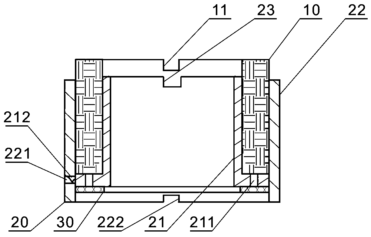
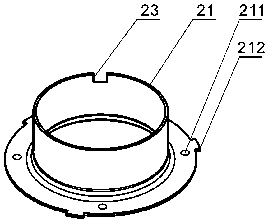
[0034] refer to figure 1 , Figure 6 , the present invention is arranged between the first PCB board 50 and the second PCB board 60, the first electrical contact region 51 and the second electrical contact region 52 are arranged on the first PCB board 50, and the second electrical contact region 52 is arranged on the second PCB board 60 Three electrical contact regions 62 , and the third electrical contact region 62 is provided with an adhesive structure 61 .

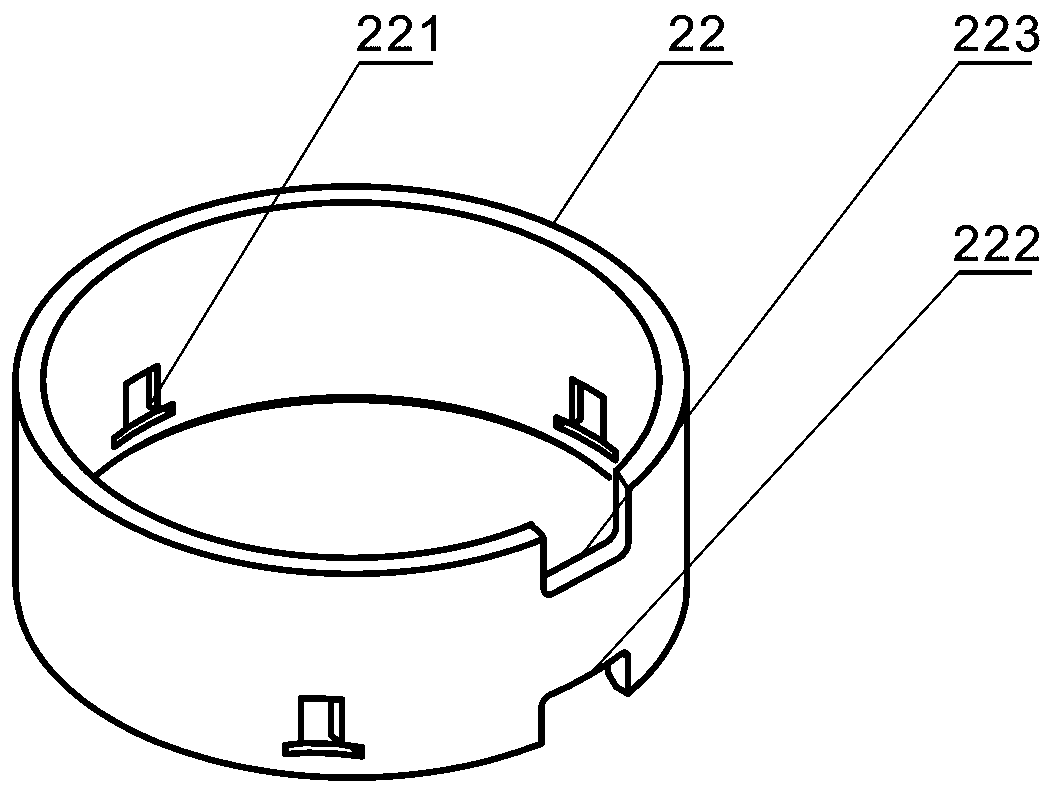
[0035] During operation, the elastic contact ring 10 is in contact with the first electrical contact area 51 on the first PCB board 50, the first gap 14 of the elastic contact ring 10, the second gap 23 of the inner shell 21 on the tray 20 and the first gap 23 on the outer shell 22. The three gaps ( 223 ) are used to accommodate the second electrical contact area 52 .

[0036] The outer shell 22 of the tray 20 is...

Embodiment 2

[0038] The structure that the present invention is combined by cylindrical pin is used like this

[0039] refer to Figure 5 , Figure 7 , the present invention is arranged between the first PCB board 50 and the second PCB board 60, the first electrical contact region 51 and the second electrical contact region 52 are arranged on the first PCB board 50, and the second electrical contact region 52 is arranged on the second PCB board 60 There are three electrical contact regions 62 , and the third electrical contact region 62 is provided with a socket structure 63 .

[0040] During operation, the elastic contact ring 10 is in contact with the first electrical contact area 51 on the first PCB board 50, and the first gap 14 of the elastic contact ring 10 and the second gap 23 of the inner shell 21 on the tray 20 accommodate the second electrical contact area 52.

[0041] The shell 22 of the tray 20 is set on the socket structure body 63 of the second PCB board 60, positioned wi...


PUM


Abstract

An elastic shielding ring for signal transmission include an elastic contact ring, tray and conductive rubber pads or cylindrical pins, As that elastic contact re is adopted, the structure of the trayand the conductive rubber pad or the cylindrical pin, the invention is arranged between two PCB boards, The elastic contact coil is in contact with the electrical contact area of the first PCB board,the flange of the inner case is bonded with the structure of the second PCB board by the conductive adhesive pad, and the electrical contact area is in contact with the structure of the second PCB board, or the cylindrical pin is inserted in the jack structure of the second PCB board and in contact with the electrical contact area, so that the signal transmission between the two PCB boards is realized. The invention effectively solves the problem of tolerance in axial and radial directions when the PCB board is connected with the PCB board by elastic contact ring and the electric contact areaof the PCB board.

Description

technical field [0001] The invention relates to the technical field of connecting PCB boards, in particular to an elastic shielding ring for signal transmission. Background technique [0002] In the field of civil communication antennas, there are usually multiple signal connection areas on the PCB board. In order to ensure the effective transmission of signals, it is required that the connection between the PCB board and the PCB board can accommodate the tolerance in the axial and radial directions. Existing board-to-board connections are usually made using RF coaxial connectors. In order to realize the tolerance design, the selected contact form has the following characteristics: a. Use sockets or plugs at both ends, and the connection mode through the middle transfer, which is composed of three components; b. Use sockets or plugs at both ends, through welding The existing problem is that the above-mentioned structures are all in axial rigid contact, which cannot meet the...

Claims


Application Information

Patent Timeline
Patent Type & Authority Applications(China)
IPC IPC(8): H01R12/71H01R13/24H01R13/502H01R13/648H01R12/57H01R12/58H01R4/04
CPCH01R4/04H01R12/57H01R12/58H01R12/716H01R13/2414H01R13/502H01R13/648
Inventor 杜如民裔永动宋德柱邹作涛匡秀娟
Owner SHANGHAI AEROSPACE SCI & IND ELECTRIC APPLIANCE RES INST
Why Eureka
Try Eureka