Positioning and calibrating method and mobile terminal

A mobile terminal and end face technology, applied in the field of plate processing, can solve the problems of inaccurate positioning, crooked holes, affecting the production and processing efficiency of plates, etc., and achieve accurate drilling positioning, prevent deviation, improve drilling efficiency and stability. Effect

Inactive Publication Date: 2019-01-08
广州雅松商贸有限公司
View PDF0 Cites 0 Cited by
  • Summary
  • Abstract
  • Description
  • Claims
  • Application Information

AI Technical Summary

Problems solved by technology

[0002] Plates are available in various industries. When the plates are used, they are often drilled according to the needs. The traditional plate punching work mainly relies on the workers to hold the punching machine to perform manual drilling. Although this is greatly beneficial to the convenience and speed However, the existing problem is that in the process of manual drilling, because only manual experience is used to align the drill bit to the plate, people's hands are prone to shaking during drilling, which can easily If the hole is punched crookedly, the positioning will be inaccurate, which will greatly affect the processing quality and processing speed of the plate, and the traditional punching equipment is not convenient for adjusting the rotation direction and disassembling of the drill bit. Therefore, the punching has strong limitations and is inconvenient to use. , which affects the efficiency of plate production and processing, needs to be improved

Method used


Image

  • Positioning and calibrating method and mobile terminal
  • Positioning and calibrating method and mobile terminal
  • Positioning and calibrating method and mobile terminal

Examples


Embodiment Construction

[0014] Combine below Figure 1-4 The present invention will be described in detail.

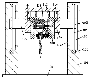
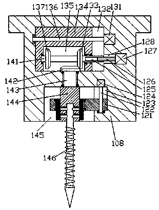
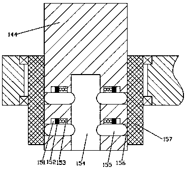
[0015] refer to Figure 1-4 , a method for positioning and calibration and a mobile terminal according to an embodiment of the present invention, comprising a chassis 100, a bracket 101 is fixed symmetrically on the top end surface of the chassis 100, and a bracket 101 is arranged between the brackets 101 on the left and right sides The main frame 107, the bottom end surface of the main frame 107 is provided with a first sliding cavity 113, and a fixing seat 108 is installed in the first sliding cavity 113, the top surface of the fixing seat 108 is in contact with the first sliding cavity. The top wall of the sliding cavity 113 is press-fitted with a buffer elastic sheet 112, and the bottom end surface of the fixing seat 108 is provided with a first concave cavity 145, and the fixing cavity 145 on the upper side of the first concave cavity 145 The seat 108 is provided with a first transmiss...


PUM


Abstract

The invention discloses a positioning and calibrating method and a mobile terminal. The mobile terminal comprises a bottom frame, supports are symmetrically and fixedly arranged on the left side and the right side of the top end face of the bottom frame, a main frame is arranged between the supports on the left side and the right side, a first sliding cavity is formed in the bottom end face of themain frame, and a mounting base is arranged in the first sliding cavity through sliding fit. A buffering elastic piece is arranged between the top end face of the mounting base and the top wall of the first sliding cavity through pressing fit, a first concave embedding cavity is formed in the bottom end face of the mounting base, and a first transmission cavity is formed in the portion, on the upper side of the first concave embedding cavity, of the mounting base. A first steering shaft is installed on the part between the first concave embedding cavity and the first transmission cavity through rotating fit, a first conical wheel is fixedly arranged at the tail end of the top of the first steering shaft, a mounting block is fixedly arranged at the tail end of the bottom of the first steering shaft, and a slot is formed in the bottom end face of the mounting block.

Description

technical field [0001] The invention relates to the technical field of plate processing, in particular to a positioning and calibration method and a mobile terminal. Background technique [0002] Plates are available in various industries. When the plates are used, they are often drilled according to the needs. The traditional plate punching work mainly relies on the workers to hold the punching machine to perform manual drilling. Although this is greatly beneficial to the convenience and speed However, the existing problem is that in the process of manual drilling, because only manual experience is used to align the drill bit to the plate, people's hands are prone to shaking during drilling, which can easily If the hole is punched crookedly, the positioning will be inaccurate, which will greatly affect the processing quality and processing speed of the plate, and the traditional punching equipment is not convenient for adjusting the rotation direction and disassembling of t...

Claims


Application Information

Patent Timeline
IPC IPC(8): B23B39/16B23B47/06B23B47/20B23Q3/12
CPCB23B39/16B23Q3/12B23Q5/10B23Q5/40
Inventor 潘军权
Owner 广州雅松商贸有限公司
Why Eureka
Try Eureka