Image processing method and device

An image processing and fixing technology, which is applied in the field of image processing, can solve the problems of inconvenient adjustment of the drill bit rotation direction and disassembly, drilling crooked, hand shaking easily, etc., so as to improve drilling efficiency and stability, and prevent deviation Effect

Inactive Publication Date: 2018-12-18
广州诗琬家居有限公司
View PDF8 Cites 0 Cited by
  • Summary
  • Abstract
  • Description
  • Claims
  • Application Information

AI Technical Summary

Problems solved by technology

[0002] After the image photo is printed, it usually needs to be installed in the photo frame. When the photo frame is produced and processed, the punching work of the traditional photo frame mainly relies on the worker to hold the punching machine to punch the hole manually. Although this is greatly conducive to the convenient and quick punching operation, but the existing problem is that in the process of manual drilling, because the drill bit is aligned with the photo frame only by manual experience, people's hands are prone to shake when drilling, so it is easy to punch the hole crookedly , which greatly affects the quality and speed of photo frame preparation, and the traditional drilling equipment is inconvenient to adjust the rotation direction and disassembly of the drill bit. Therefore, the punching has strong limitations and is inconvenient to use, which affects the production and processing efficiency of the photo frame. It needs to be improved.

Method used


Image

  • Image processing method and device
  • Image processing method and device
  • Image processing method and device

Examples


Embodiment Construction

[0014] Combine below Figure 1-4 The present invention will be described in detail.

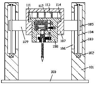
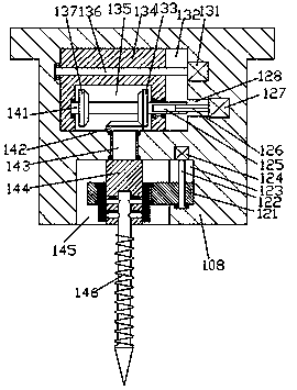
[0015] refer to Figure 1-4 , an image processing method and device according to an embodiment of the present invention, comprising a bottom plate 100, a support 101 is fixed symmetrically on the top end surface of the bottom plate 100, and a frame body is arranged between the support 101 on the left and right sides 107, a first sliding cavity 113 is provided in the bottom end surface of the frame body 107, and a fixing seat 108 is installed in the sliding fit in the first sliding cavity 113, and the top surface of the fixing seat 108 and the first The top wall of the sliding chamber 113 is press-fitted with a cushioning spring pressing piece 112, and a first concave cavity 145 is arranged in the bottom end surface of the fixing seat 108, and the fixing seat on the upper side of the first concave cavity 145 108 is provided with a first transmission cavity 132, and the part between the first...


PUM


Abstract

The invention discloses an image processing method and device. The image processing device comprises a bottom plate, the top end face of the bottom plate is fixedly provided with support seats in a left and right symmetrical manner, a rack body is arranged between the left side support seat and the right side support seat, the bottom end face of the rack body is internally provided with a first sliding moving cavity, the first sliding moving cavity is internally provided with an installing fixing seat in a sliding matching manner, buffer spring press pieces are installed between the top end face of the installing fixing seat and the top wall of the first sliding moving cavity in a jacking-pressing matching manner, the bottom end face of the installing fixing seat is internally provided with a first concave cavity, the part, on the upper side of the first concave cavity, of the installing fixing seat is internally provided with a first conveying cavity, the part between the first concave cavity and the first conveying cavity is provided with a first rotating pin shaft in a rotating matching manner, the tail end of the top of the first rotating pin shaft is fixedly provided with a first cone-shaped wheel, the tail end of the bottom of the first rotating pin shaft is fixedly provided with an installing fixing block, and the bottom end face of the installing fixing block is internally provided with a socket.

Description

technical field [0001] The present invention relates to the technical field of image processing, in particular to an image processing method and device. Background technique [0002] After the image photo is printed, it usually needs to be installed in the photo frame. When the photo frame is produced and processed, the punching work of the traditional photo frame mainly relies on the worker to hold the punching machine to punch the hole manually. Although this is greatly conducive to the convenient and quick punching operation, but the existing problem is that in the process of manual drilling, because the drill bit is aligned with the photo frame only by manual experience, people's hands are prone to shake when drilling, so it is easy to punch the hole crookedly , which greatly affects the quality and speed of photo frame preparation, and the traditional punching equipment is inconvenient to adjust the direction of rotation and disassembly of the drill bit. Therefore, the ...

Claims


Application Information

Patent Timeline
IPC IPC(8): B26F1/16B26D7/26
Inventor 时建华
Owner 广州诗琬家居有限公司
Why Eureka
Try Eureka