

Engineering surveying instrument positioning device
A technology of positioning device and surveying instrument, which is applied in the direction of measuring device, workpiece clamping device, measuring instrument, etc., can solve the problems of inconvenient use and complicated operation, and achieve the effect of convenient use, simple overall structure and avoidance of deviation.
- Summary
- Abstract
- Description
- Claims
- Application Information
AI Technical Summary
Problems solved by technology
Method used
Image

Examples
Embodiment 1
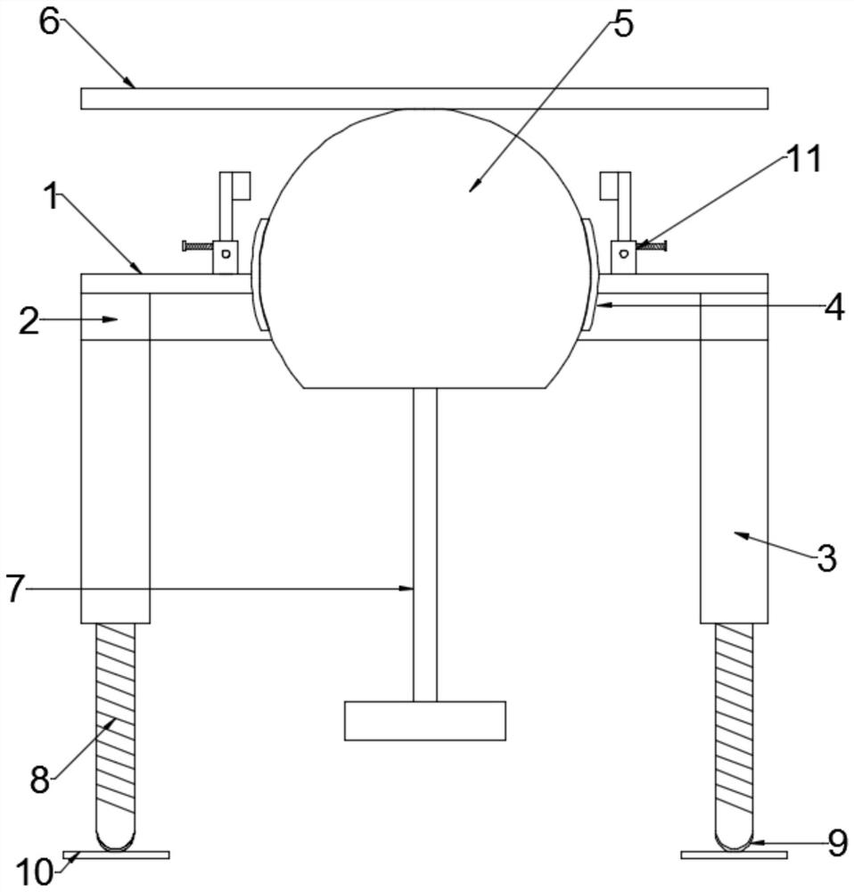
[0020] see Figure 1~3 , in an embodiment of the present invention, a positioning device for an engineering surveying instrument includes a base plate 1, a support cylinder 3 and a placement plate 6, the lower end of the base plate 1 is rotatably connected to a support cylinder 3 through a bearing seat 2, and the middle part of the base plate 1 runs through An annular cavity 4 is provided, and a ball seat 5 is arranged in a movable fit connection in the annular cavity 4. The upper end of the ball seat 5 is horizontally fixedly connected with a placement plate 6, and the lower end of the ball seat 5 is vertically fixedly connected with a suspender 7. The end of the suspender 7 away from the ball seat 5 is fixedly connected with a counterweight lead weight, and the bottom plate 1 is connected to the periphery of the annular cavity 4 and is provided with a plurality of sets of stoppers for movingly pressing the ball seat 5 Card 11.
[0021] The support cylinders 3 are arranged i...
Embodiment 2
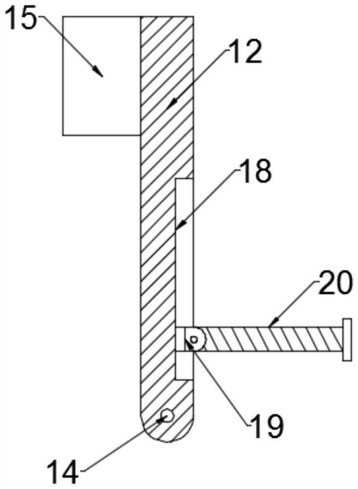
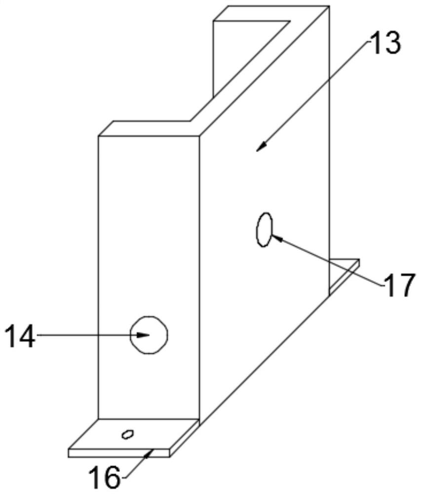
[0025] see image 3 , in an embodiment of the present invention, a positioning device for an engineering surveying instrument. On the basis of Embodiment 1, the limit card 11 includes a rotating seat 13 fixedly connected to the bottom plate 1 and connected to the rotating seat through a rotating shaft 14 in rotation. The rotating rod 12 on 13, the end of the rotating rod 12 away from the rotating seat 13 is fixedly connected with an anti-slip block 15, the anti-slip block 15 is block rubber, and the anti-slip block 15 and the ball seat 5 are oppositely arranged The surface of the anti-slip block 15 and the ball seat 5 can be bonded by the rotation of the rotating rod 12, and multiple groups of ball seats 5 are pressed on the surface of the ball seat 5, which can prevent the rotation of the ball seat 5 by frictional force and ensure the stability of the placement plate 6. Level.
[0026] The rotating seat 13 is a "U"-shaped bent metal piece, the opening of the rotating seat 13...
PUM
 Abstract
Description
Claims
Application Information