Anti-leakage storage hopper
An anti-leakage, storage bucket technology, applied in loading/unloading, container, packaging and other directions, can solve the problem of powdery materials easily escaping dust and other problems, and achieve the effect of solving material escape
- Summary
- Abstract
- Description
- Claims
- Application Information
AI Technical Summary
Problems solved by technology
Method used
Image

Examples
Embodiment 1
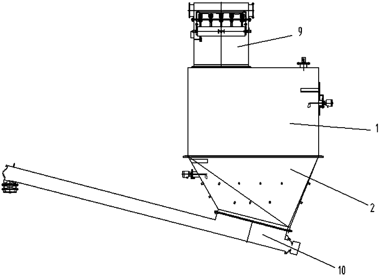
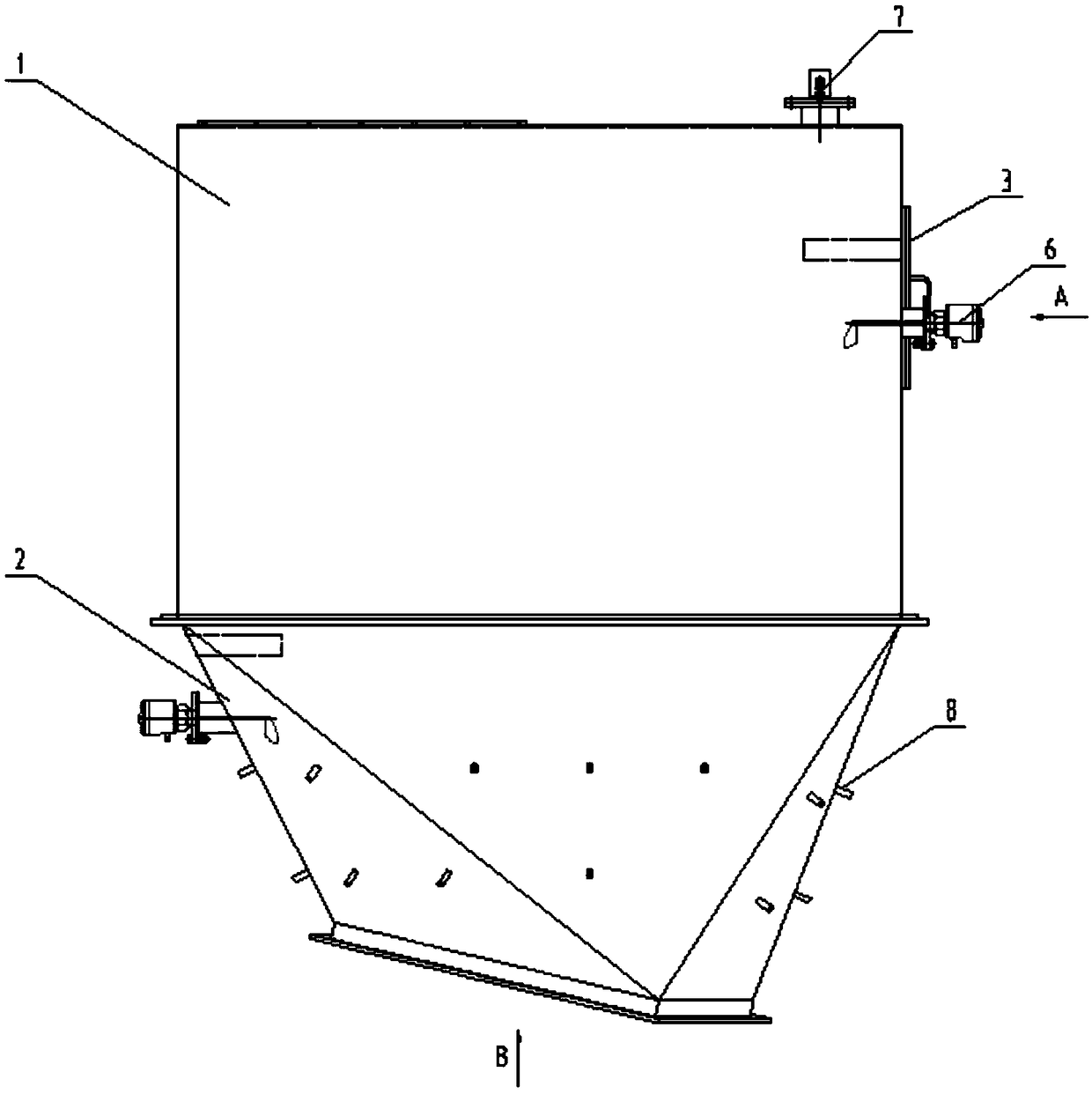
[0031] Such as Figure 3 to Figure 6As shown, in this embodiment, the inclination angle of the discharge port 11 relative to the arrangement direction of the upper bucket body 1 is 35°, which is greater than 0°. The direction of the discharge pipeline 10 is inclined downward from front to rear, and the storage bucket is located at the rear end of the discharge pipeline 10 to feed materials forward. The lower bucket body 2 includes a lower triangular plate 15 and an upper triangular plate 14. The lower triangular plate 15 includes four lower triangular plates 15 in four directions, front, rear, left, and right. The upper triangular plate 14 includes four front, rear, left, and right sides. The four upper triangular plates 14 in the direction, the lower triangular plate 15 and the upper triangular plate 14 are arranged at intervals, the lower side of the lower triangular plate 15 is welded and fixed on the side of the discharge port 11, the lower The other two sides of the tria...
Embodiment 2
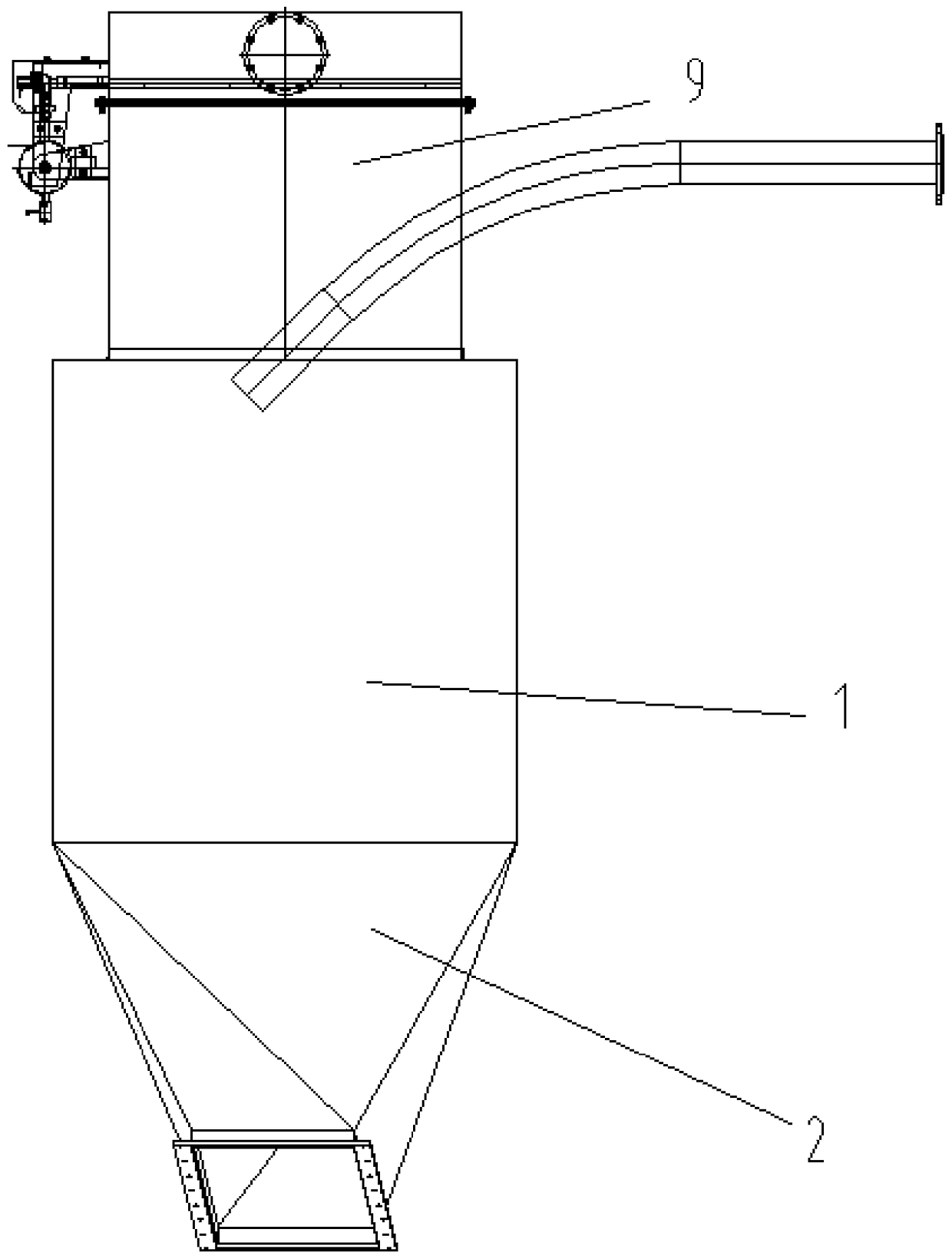
[0033] Such as Figure 7 to Figure 8 As shown, in this embodiment, the inclination angle of the discharge port 11 relative to the arrangement direction of the upper bucket body 1 is 19.5°, which is greater than 0°. The direction of the discharge pipeline 10 is inclined downward from front to rear, and the storage bucket is located at the rear end of the discharge pipeline 10 to feed materials forward. The lower bucket body 2 includes a lower triangular plate 15 and an upper triangular plate 14. The lower triangular plate 15 includes four lower triangular plates 15 in four directions, front, rear, left, and right. The upper triangular plate 14 includes four front, rear, left, and right sides. The four upper triangular plates 14 in the direction, the lower triangular plate 15 and the upper triangular plate 14 are arranged at intervals, the lower side of the lower triangular plate 15 is welded and fixed on the side of the discharge port 11, the lower The other two sides of the t...
Embodiment 3
[0035] The inclination angle of the discharge port 11 relative to the arrangement direction of the upper bucket body 1 is 0°, the direction of the discharge pipeline 10 is inclined from front to rear, and the storage bucket is located at the rear end of the discharge pipeline 10 to feed materials forward. Described lower bucket body 2 comprises front side plate 18, left side plate 17, right side plate 19 and rear side plate 16, and described front side plate 18 and described rear side plate 16 are all trapezoidal plates, and the trapezoidal plate The lower bottom is welded on the bottom of the lower hopper, the upper bottom of the trapezoidal plate is welded on the front side and the rear side of the discharge port 11, the left side plate 17 includes a lower left triangular plate and an upper left triangular plate, the lower left The three sides of the triangular plate are respectively welded to the side of the front side plate 18, the side of the discharge port 11 and the side...
PUM
 Abstract
Description
Claims
Application Information
 - R&D
- Intellectual Property
- Life Sciences
- Materials
- Tech Scout
- Unparalleled Data Quality
- Higher Quality Content
- 60% Fewer Hallucinations
Browse by: Latest US Patents, China's latest patents, Technical Efficacy Thesaurus, Application Domain, Technology Topic, Popular Technical Reports.
© 2025 PatSnap. All rights reserved.Legal|Privacy policy|Modern Slavery Act Transparency Statement|Sitemap|About US| Contact US: help@patsnap.com