A car seat shock absorber

A shock absorbing device and car seat technology, which is applied to seat suspension devices, vehicle seats, seat heating/ventilation devices, etc., can solve the problems of reduced driving comfort, high cost, and high fuel consumption, and achieve changes Effects of cushioning force characteristics, improvement of practical performance, and cost saving of fuel consumption

Active Publication Date: 2021-07-13
SHAOGUAN COLLEGE
View PDF5 Cites 0 Cited by
  • Summary
  • Abstract
  • Description
  • Claims
  • Application Information

AI Technical Summary

Problems solved by technology

In the existing automobiles, the car seat can be adjusted front and rear and the backrest angle, but the structure is complicated, and the height adjustment of the seat cannot be realized, which cannot meet the needs of people of different heights for seat height adjustment, and affects the driving experience. Comfort and Safety
In addition, shock absorbers are installed under the seats, and ordinary shock absorbers generally have constant cushioning force characteristics, so low cushioning force characteristics can improve driving comfort, but cannot ensure vehicle stability
On the contrary, high cushioning force characteristics can maintain the stable posture of the vehicle, but lead to a decrease in driving comfort
Thus, conventional shock absorbers cannot control the cushioning force characteristics in response to changes in road conditions or vehicle attitude
[0003] In addition, when seat heating is required, it is necessary to install a separate heating resistance wire inside the seat or use the car air conditioner to heat it, so that the fuel consumption is high and the cost is high.

Method used


Image

  • A car seat shock absorber
  • A car seat shock absorber
  • A car seat shock absorber

Examples


Embodiment Construction

[0021] In order to further understand the features, technical means, and specific objectives and functions achieved by the present invention, the present invention will be further described in detail below in conjunction with the accompanying drawings and specific embodiments.

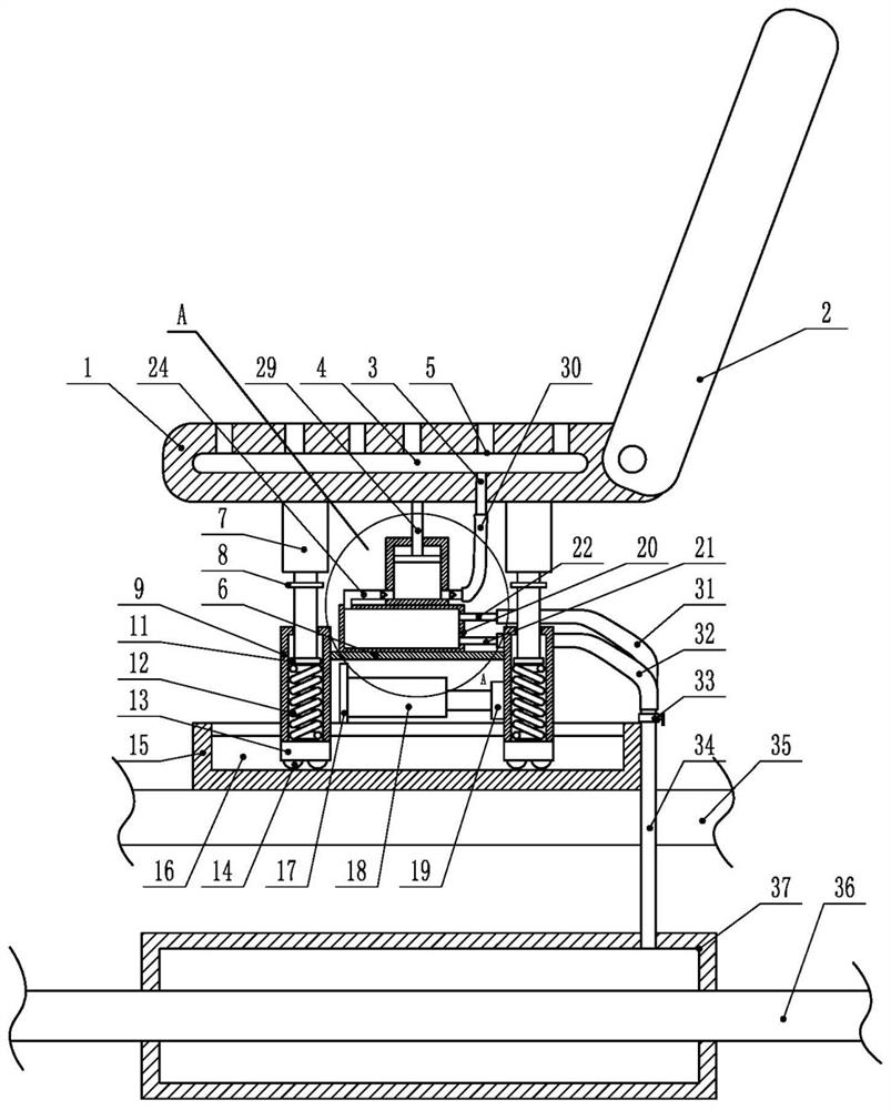
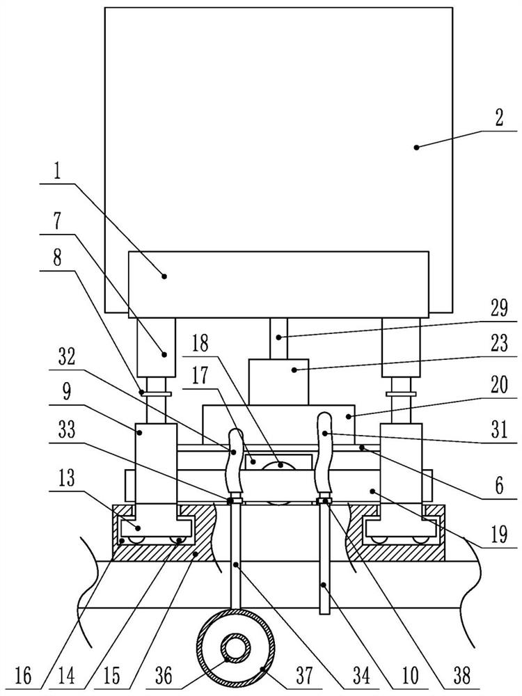
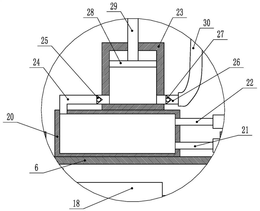
[0022] as attached figure 1 , 2 As shown in and 3, the present invention discloses a shock absorbing device for a car seat, comprising a seat 1, a backrest 2 hinged on one side of the seat 1, a base 15 is provided below the seat 1, and four sides of the bottom surface of the seat 15 Each corner position is respectively provided with a buffering shock absorbing mechanism to form four buffering shock absorbing mechanisms altogether, and base 15 is provided with chute 16. By setting four cushioning and damping mechanisms, which are respectively located at the four corners of the seat, the stability and balance during use are guaranteed.

[0023] Described buffer damping mechanism comprises electric tele...


PUM


Abstract

A shock absorbing device for a car seat, comprising a seat, one side of the seat is hinged with a backrest, a base is provided under the seat, and a buffer and shock absorbing mechanism is respectively provided at four corners of the bottom surface of the seat to form a total of four A buffer and shock absorbing mechanism, the base is provided with a chute; the buffer and shock absorbing mechanism includes an electric telescopic rod, a spring barrel, a slider and a spring, the spring and the slider are arranged in the spring barrel, and the upper end of the spring is connected with the bottom surface of the slider , the lower end is connected with the bottom surface of the spring tube, the lower end of the telescopic slider of the electric telescopic rod stretches into the spring tube and is fixedly connected with the upper surface of the slide block, the bottom of the spring tube is contained in the chute, and the electric telescopic rod is connected with the automobile power supply. The invention has good shock absorption performance and ventilation performance, and improves the comfort of use.

Description

technical field [0001] The invention belongs to the technical field of automobiles, in particular to a shock absorbing device for an automobile seat. Background technique [0002] Generally, the same car will often be driven by different people, and different people have different requirements for the height of the driver's seat due to their different heights. In the existing automobiles, the car seat can be adjusted front and rear and the backrest angle, but the structure is complicated, and the height adjustment of the seat cannot be realized, which cannot meet the needs of people of different heights for seat height adjustment, and affects the driving experience. Comfort and safety. In addition, shock absorbers are installed under the seats, and ordinary shock absorbers generally have constant cushioning force characteristics, so low cushioning force characteristics can improve driving comfort, but cannot ensure vehicle stability. On the contrary, a high cushioning forc...

Claims


Application Information

Patent Timeline
Patent Type & Authority Patents(China)
IPC IPC(8): B60N2/06B60N2/16B60N2/54B60N2/56
CPCB60N2/06B60N2/16B60N2/54B60N2/5621
Inventor 李锐伟黄莹李小平黄晨华肖耘亚
Owner SHAOGUAN COLLEGE
Why Eureka
Try Eureka