A Pneumatically Driven Retrievable Rocket Landing Support Mechanism
A technology of pneumatic drive and supporting mechanism, which is applied in the field of aerospace and can solve problems such as poor stability and large launch air resistance
- Summary
- Abstract
- Description
- Claims
- Application Information
AI Technical Summary
Problems solved by technology
Method used
Image
Examples
specific Embodiment approach 1
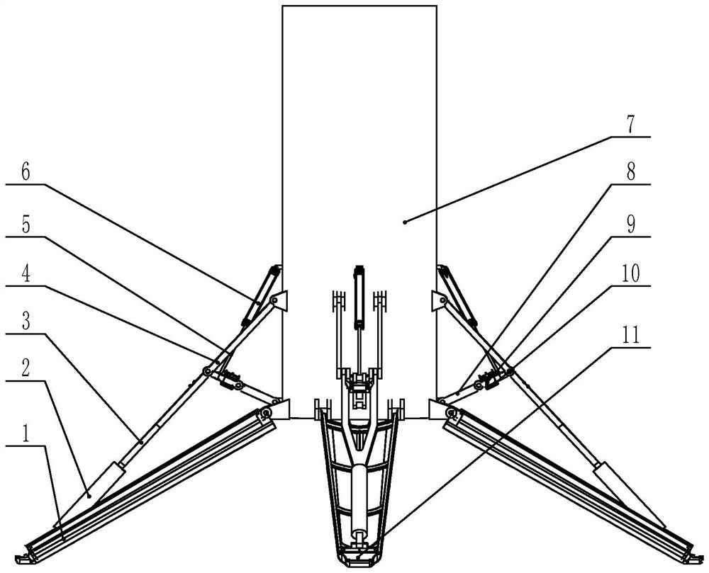
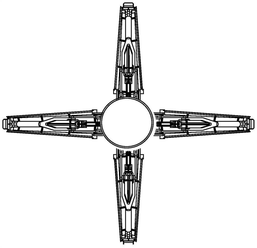
[0012] Specific implementation mode one: combine figure 1 with figure 2 Describe this embodiment, a pneumatically driven recoverable rocket landing support mechanism described in this embodiment, which includes four foldable and foldable integrated expandable mechanisms with cushioning characteristics, and the four foldable and retractable integrated mechanisms with cushioning characteristics The fully deployable mechanism is uniformly arranged on the outer wall of the bottom of the rocket body 7 along the circumferential direction, and each of the foldable and retractable integrated deployable mechanisms with cushioning properties includes a landing leg 1, a buffer assembly, a pneumatic drive assembly and a locking Assembly, one end of the landing leg 1 is hinged to the side wall at the bottom of the rocket body 7, the upper surface of the other end of the landing leg 1 is connected to the rocket body 7 through the buffer assembly, and one end of the locking assembly is conn...
specific Embodiment approach 2
[0014] Specific implementation mode two: combination figure 1 with figure 2 Describe this embodiment, the buffer assembly of a pneumatically driven recoverable rocket landing support mechanism described in this embodiment includes a hydraulic buffer 2, a buffer support rod 3 and a rocket body support rod 4, the bottom of the hydraulic buffer 2 and the landing leg 1 The upper surface of the other end is hinged, one end of the buffer support rod 3 is fixedly connected to the piston of the hydraulic buffer 2, the other end of the buffer support rod 3 is hinged to one end of the arrow body support rod 4, and the other end of the arrow body support rod 4 One end is hinged with the outer wall of the rocket body 7 . The buffer support rod 3 reasonably distributes the structural strength by adopting a Y-shaped structure. Other components and connections are the same as those in the mechanism implementation mode 1.
specific Embodiment approach 3
[0015] Specific implementation mode three: combination figure 1 with figure 2 Describe this embodiment. The locking assembly of a pneumatically driven recoverable rocket landing support mechanism described in this embodiment includes a driving intermediate link 8, an auxiliary intermediate link 9 and a locker 10. One end of the driving intermediate link 8 is connected to the The bottom of the rocket body 7 is hinged, the other end of the driving intermediate link 8 is hinged with one end of the auxiliary intermediate link 9, the other end of the auxiliary intermediate link 9 is hinged with the other end of the buffer support rod 3, and the locking device 10 is installed on The connection between the driving intermediate link 8 and the auxiliary intermediate link 9. Other compositions and connections are the same as those in Embodiment 1 or 2.
PUM
 Abstract
Description
Claims
Application Information
 - R&D
- Intellectual Property
- Life Sciences
- Materials
- Tech Scout
- Unparalleled Data Quality
- Higher Quality Content
- 60% Fewer Hallucinations
Browse by: Latest US Patents, China's latest patents, Technical Efficacy Thesaurus, Application Domain, Technology Topic, Popular Technical Reports.
© 2025 PatSnap. All rights reserved.Legal|Privacy policy|Modern Slavery Act Transparency Statement|Sitemap|About US| Contact US: help@patsnap.com


