An interleaved resonant converter and control method

A technology for resonant converters and transformers, applied in control/regulation systems, converting DC power input to DC power output, instruments, etc., can solve the problems of narrow output voltage range and large control frequency range of resonant converters, and achieve output resolution Effects of narrow voltage range, wide input voltage range, and reduced drive loss and turn-off loss

Inactive Publication Date: 2019-01-11
HANGZHOU ZHONGHEN ELECTRIC CO LTD
View PDF4 Cites 3 Cited by
  • Summary
  • Abstract
  • Description
  • Claims
  • Application Information

AI Technical Summary

Problems solved by technology

[0004] In order to overcome the deficiencies of the prior art, the object of the present invention is an interleaved resonant converter and a control method, which solve the problems of narrow output voltage range and large control frequency range of the resonant converter

Method used


Image

  • An interleaved resonant converter and control method
  • An interleaved resonant converter and control method
  • An interleaved resonant converter and control method

Examples


Embodiment 1

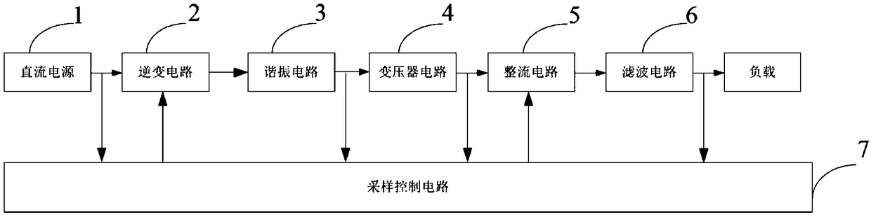
[0045] The present invention provides an interleaved resonant converter, such as figure 1 As shown, the interleaved resonant converter includes a DC power supply 1, an inverter circuit 2, a resonant circuit 3, a transformer circuit 4, a rectifier circuit 5, a filter circuit 6, a sampling control circuit 7 and a load, and the output terminal of the DC power supply 1 is connected to the inverter circuit 2, the output end of the inverter circuit 2 is connected to the input end of the resonant circuit 3, the output end of the resonant circuit 3 is connected to the primary side of the transformer circuit 4, and the secondary side of the transformer circuit 4 is connected to the input end of the rectification circuit 5, rectification The output end of the circuit 5 is connected to the input end of the filter circuit 6, the output end of the filter circuit 6 is connected to the load, the control end of the sampling control circuit 7 is respectively connected to the control end of the ...

Embodiment 2

[0089]The difference between this embodiment and Embodiment 1 lies in the specific connection relationship in the transformer circuit 4. Similarly, the transformer circuit 4 in this embodiment includes at least three transformers. interconnected.

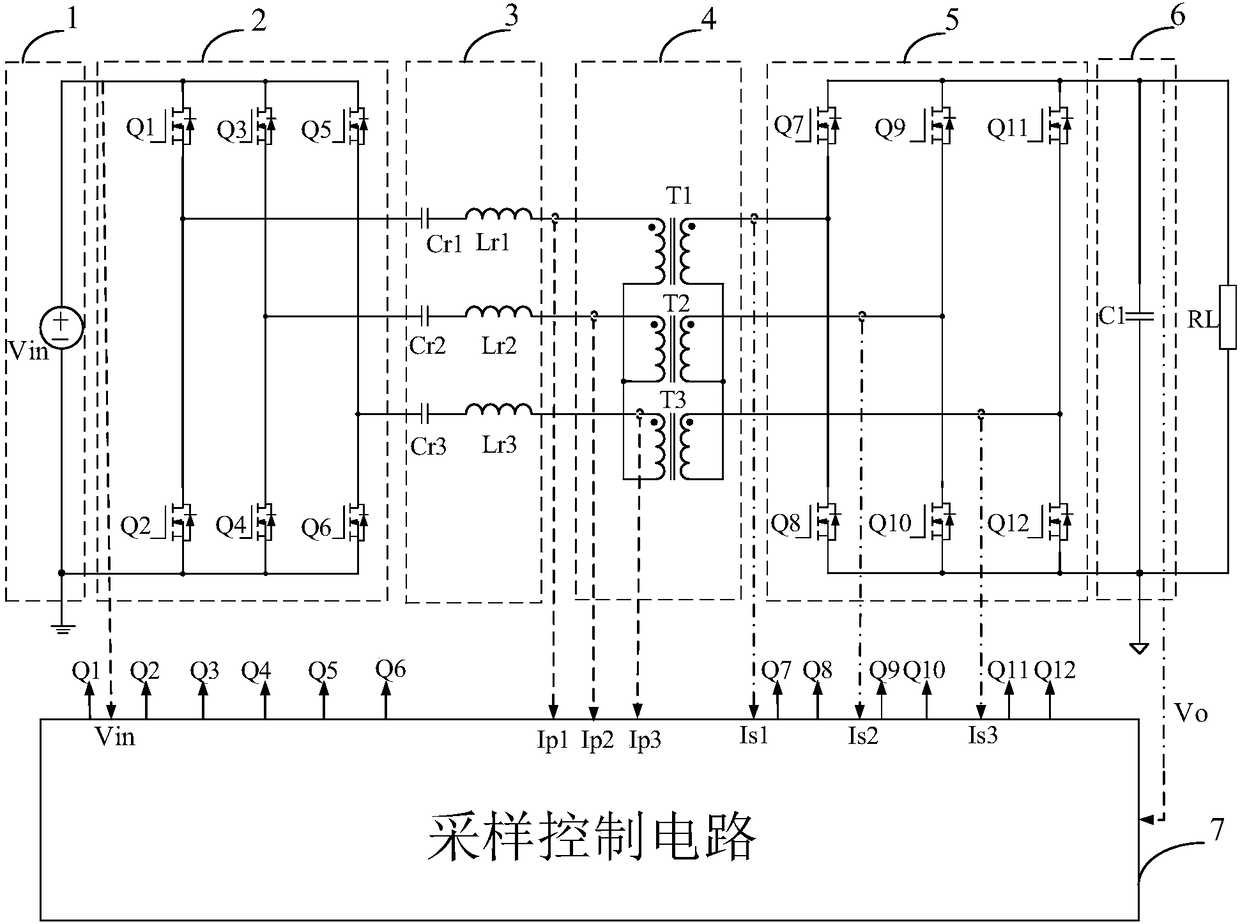
[0090] Take the transformer circuit 4 including three transformers as an example, as Figure 9 As shown, the transformer circuit 4 includes a first transformer T1, a second transformer T2 and a third transformer T3, the primary side end of the first transformer T1 with the same name is connected to the first resonant inductor Lr1, and the other end of the primary side of the first transformer T1 is connected to the second The same name terminal of the primary side of the transformer T2, the same name terminal of the primary side of the second transformer T2 is connected to the second resonant inductor Lr2, the other end of the primary side of the second transformer T2 is connected to the same name terminal of the primary side of the...

Embodiment 3

[0093] The difference between this embodiment and Embodiment 2 lies in the specific connection relationship in the resonant circuit 3. Similarly, in this embodiment, the resonant circuit 3 includes at least three groups of resonant modules, each group of resonant modules includes a resonant inductor and a resonant capacitor, and the resonant capacitor is connected in parallel. On the primary side of the transformer circuit 4 , one end of the resonant inductance is connected to the common point of the first primary switching tube and the second primary switching tube in the corresponding group, and the other end of the resonant inductance is connected to the primary side of the transformer circuit 4 .

[0094] The working principle of the resonant circuit 3 and the interleaved resonant converter in this embodiment is the same as that of the resonant circuit 3 and the interleaved resonant converter in the first embodiment, and will not be repeated here, and the output voltage rang...


PUM


Abstract

The invention discloses an interleaved resonant converter and a control method. The interleaved resonant converter comprises a DC power supply, an inverter circuit, a resonant circuit, a transformer circuit, a rectifier circuit and a filter circuit. The resonant converter further comprises a sampling control circuit which is respectively connected with the primary side orand the secondary side ofthe inverter circuit, the rectifier circuit, the filter circuit and the transformer circuit. The output voltage is regulated by sampling control circuit, frequency conversion control inverter circuitand delay control rectifier circuit, the delay control is realized based on the zero-crossing point delay in the secondary current or the primary current to turn off the corresponding secondary switching transistor. The delay control increases the energy in the resonant circuit, which makes the interleaved resonant converter have the boost characteristic. The interleaved resonant converter reducesthe control frequency range greatly to realize the wide input voltage range andor the wide output voltage range, thus solving the problem the the output voltage range of the resonant converter is narrow and the control frequency range is large.

Description

technical field [0001] The invention relates to the technical field of power electronics applications, in particular to an interleaved resonant converter and a control method. Background technique [0002] Resonant Converter Due to its simple circuit topology, and its ability to achieve soft switching over the full load range, resonant converters are widely used in state-of-the-art power supplies that provide the highest power density and efficiency. Although the resonant converter has many advantages such as soft switching of switching devices, low switching loss, high efficiency and superior EMI (Electromagnetic Interference, electromagnetic interference) performance compared to hard switching, the defects are still obvious, such as the input voltage range of the resonant converter Or the output voltage range is narrow. [0003] Due to the limitations of existing technologies, the current mainstream method is to widen the output voltage range or / output voltage range of th...

Claims


Application Information

Patent Timeline
Patent Type & Authority Applications(China)
IPC IPC(8): H02M3/335
CPCH02M3/33576H02M1/0058Y02B70/10
Inventor 韦忠杰韦康郑益群
Owner HANGZHOU ZHONGHEN ELECTRIC CO LTD
Why Eureka
Try Eureka