Lens driving device

A lens driving device and lens driving technology, applied in installation, optics, instruments, etc., can solve the problems of increasing driving loss, slowing lens moving speed, slow response, etc., reducing driving loss, improving response performance, and satisfying The effect of fine-tuning the action

Inactive Publication Date: 2006-08-09
SHICOH MOTOR (SHANGHAI) CO LTD
View PDF2 Cites 4 Cited by
  • Summary
  • Abstract
  • Description
  • Claims
  • Application Information

AI Technical Summary

Problems solved by technology

[0003] However, the mechanical lens driving device of the prior art, which converts the rotary motion into a linear motion by using a spiral method to move the lens to the optical axis, can achieve the required function on a large camera, but it is used in a portable camera. In small cameras, the direction of thrust and the direction of lens movement are not consistent, resulting in greater drive loss; at the same time, it causes defects such as slowed down of lens movement and slow response

Method used


Image

  • Lens driving device
  • Lens driving device
  • Lens driving device

Examples


Embodiment Construction

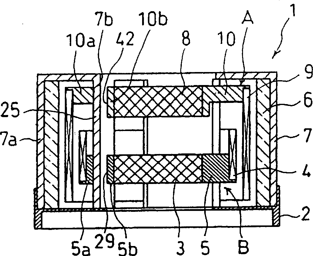
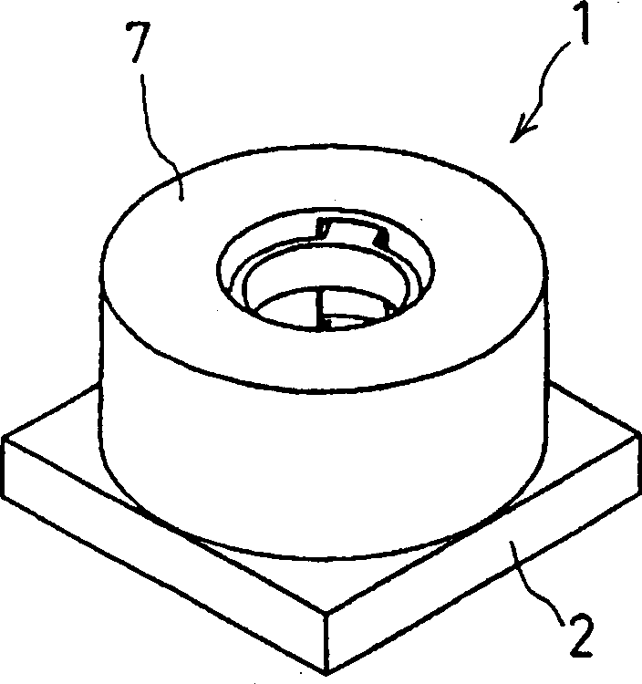
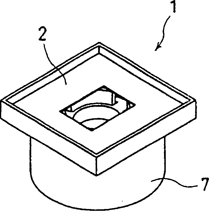
[0032] See Figure 1 to Figure 5 As shown, they are schematic structural diagrams of the first embodiment of the lens driving device of the present invention. The lens driving device 1 of the present invention is a lens driving device that can be assembled in an auto-focus camera in a mobile phone. The lens driving device 1 of the present invention consists of a base 2, a ring mouth 7 arranged on the base 2, a magnet 6 located in the ring mouth 7, and a first lens driving part A and a second lens driving part A which are jointly arranged in the magnet 6 and the ring mouth 7. Composed of lens driving part B. The first lens driving part A is arranged inside the magnet 6; the second lens driving part B is concentrically arranged inside the first lens driving part A, and they share the same ring mouth 7 and the magnet 6, thereby reducing the size of the lens driving device The overall outer diameter of the lens drive device can be miniaturized.

[0033] A circular groove 21 is ...


PUM


Abstract

The drive set includes a base, a collar extension setup on the base, and a magnet located inside the collar extension. Characters are that the drive set also includes a first and a second lens drive modules setup inside same collar extension and the magnet jointly. The first lens drive module consists of first coil inside the magnet, first lens supporter and lens setup inside the first coil. The second lens drive module consists of second coil inside the first coil, second lens supporter and lens setup inside the second coil. Two drive modules share the collar extension and the magnet so as to make drives set miniaturization. Friction tabling between lens supporters and the collar extension makes supporters possible to move smoothly. Installed spring guarantees stabilizing force for the lens supporters. Thus, it is difficult to shake lens supporters even if camera is suffered from bump or impulsion. Features are: excellent impact resistance, simplified structure and few parts.

Description

technical field [0001] The invention relates to a lens driving device, in particular to a lens driving device installed in a small camera or a mobile phone to drive a variable focus lens and an automatic focus lens. Background technique [0002] The lens driving device in the prior art usually has two functions, that is, after using the zoom lens and the focus lens, it can perform auto-focus (auto-zoom) and magnification change. Such a lens driving device usually converts the rotary motion in the form of a spiral into a linear motion to move the lens toward the optical axis. Please refer to the announcement published in Japanese Patent No. 1996-140523 (Heisei 7-140523) for the above-mentioned technical content. [0003] However, the mechanical lens driving device of the prior art, which converts the rotary motion into a linear motion by using a spiral method to move the lens to the optical axis, can achieve the required function on a large camera, but it is used in a portab...

Claims


Application Information

Patent Timeline
Patent Type & Authority Applications(China)
IPC IPC(8): G02B7/02G02B7/04G03B17/02
Inventor 白木学浅川聪关口直树吉江守正
Owner SHICOH MOTOR (SHANGHAI) CO LTD
Why Eureka
Try Eureka