Closing device for drawers

Active Publication Date: 2012-06-26
KNAPE & VOGT MFG
View PDF20 Cites 45 Cited by
  • Summary
  • Abstract
  • Description
  • Claims
  • Application Information

AI Technical Summary

Benefits of technology

[0026]The following discloses example of improved closing devices which impart a mechanical advantage that results in the application of a biasing force that is not increased in a consistent or uniform manner when compared to the linear movement of a latching member that is coupled to one of the drawer slide members. Thus, instead of continuing to increase the biasing force to be applied at the disengagement/engagement point of the latching member at a uniform linear rate, the disclosed example closing device has a biasing member but is configured to have a latching member that does not move at the same rate as an the biasing member is lengthened. Thus, the increase in the biasing force is at a reduced rate per unit length of movement as the drawer slide continues to move outward until t

Problems solved by technology

This results in operation with an on-off or jerky feel with respect to the influence of the spring when the latching member enters and exits the armed position.
This construction tends to result in a jerking motion that is unsettling to the user and may cause the contents of the drawer to shift abruptly.
The high spring force

Method used


Image

  • Closing device for drawers
  • Closing device for drawers
  • Closing device for drawers

Examples


Example

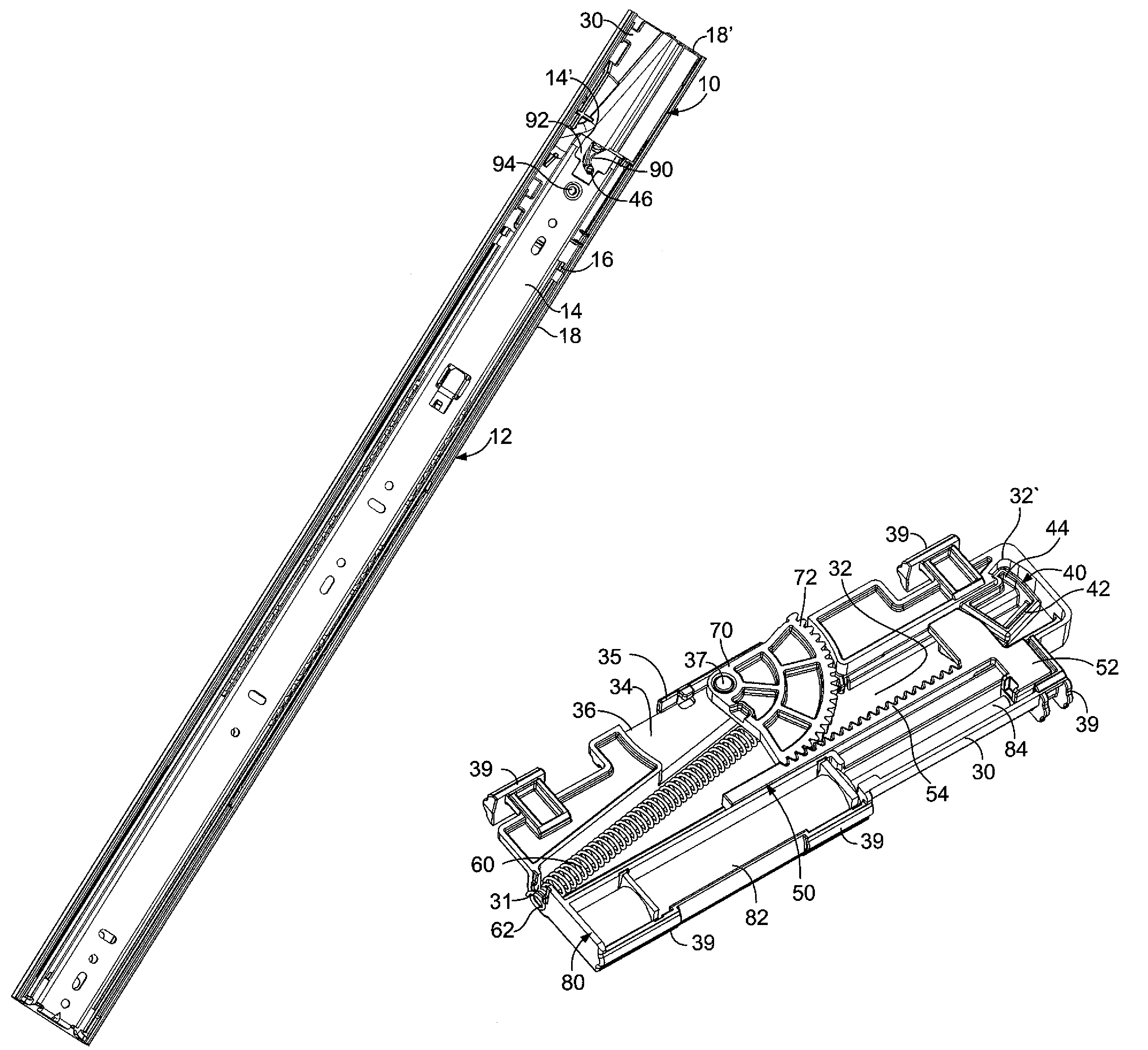
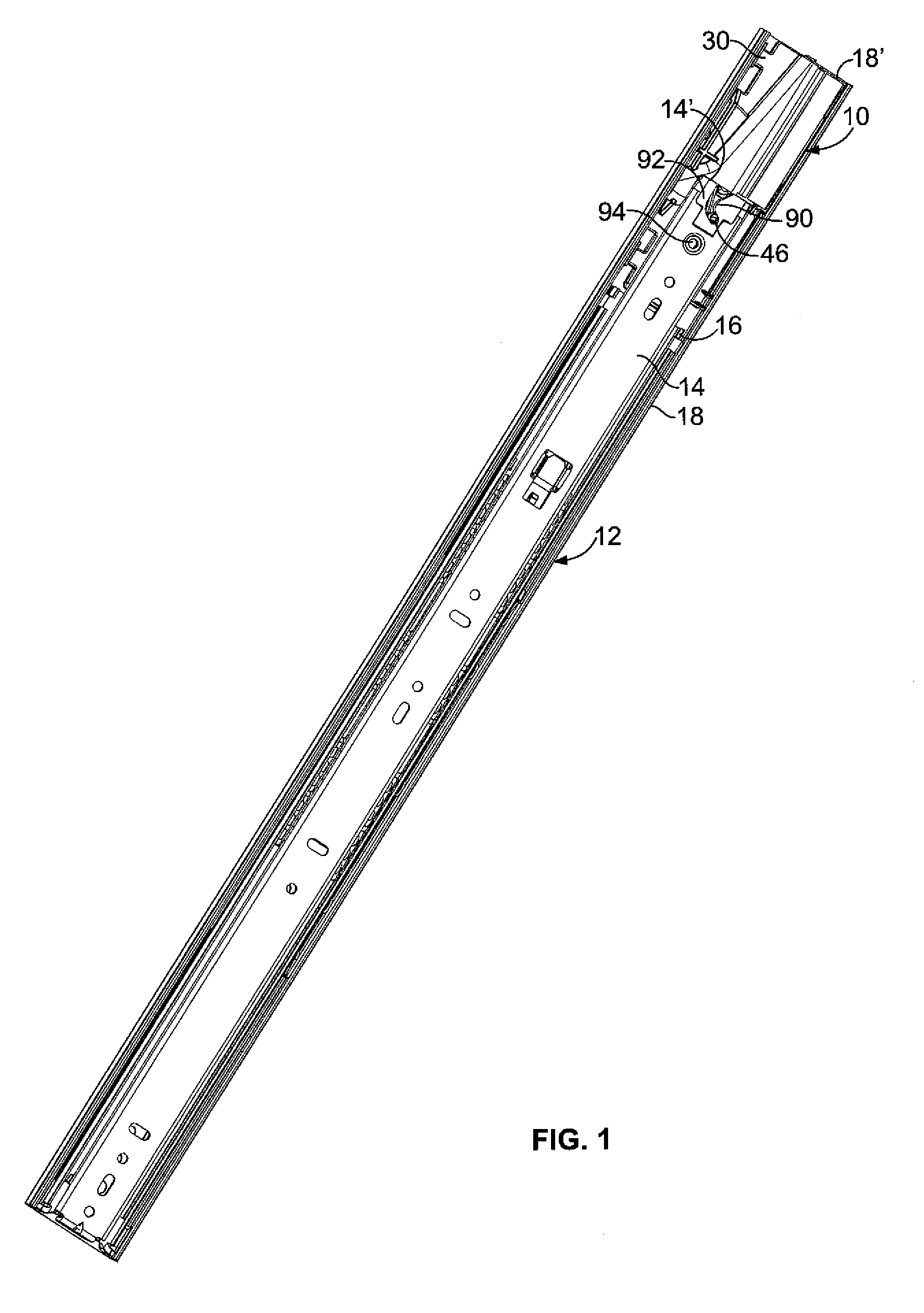
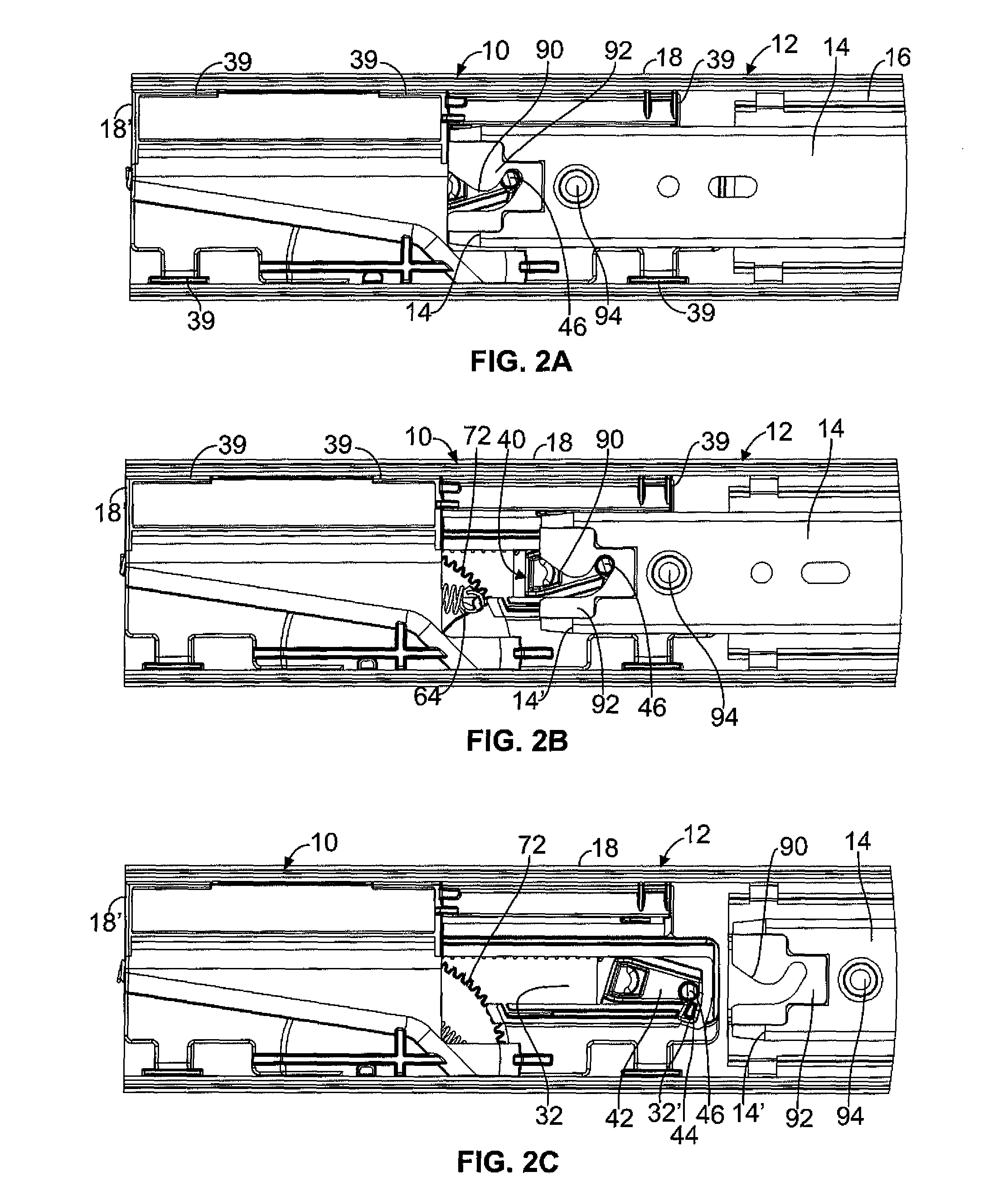
[0030]Although the following discloses example closing devices shown for use with drawers coupled to drawer slides, persons of ordinary skill in the art will appreciate that the teachings of this disclosure are in no way limited to the specific examples illustrated. On the contrary, it is contemplated that the teachings of this disclosure may be implemented in alternative configurations and environments. In addition, although the example closing devices described herein are shown in conjunction with a particular configuration of a drawer slide assembly, those having ordinary skill in the art will readily recognize that the componentry of the example closing devices may be used in a drawer slide, whether of a side mount or undermount construction, or may be mounted independently of a drawer slide.

[0031]Referring to FIGS. 1-5C, it will be appreciated that a first example closing device of the present disclosure generally may be embodied within numerous configurations within a device t...


PUM


Abstract

A closing device that includes a latching member that when moved a given distance utilizes a gear to effect a mechanical advantage that results in an end of a biasing member being moved less than the given distance. The biasing member is used in moving a first drawer slide member to a closed position relative to a second drawer slide member, and use of the gear and the resulting mechanical advantage provide a smoother transition when the first drawer slide member is engaged or disengaged from the closing device.

Description

CROSS-REFERENCE TO RELATED APPLICATION[0001]This application claims priority from U.S. Provisional Patent Application No. 61 / 257,927, filed Nov. 4, 2009, the disclosure of which is hereby incorporated by reference in its entirety.FIELD OF THE DISCLOSURE[0002]The present invention generally relates to closing devices that often are incorporated into drawer slides otherwise known as self-closing drawer slides. Such drawer slides tend to be used in articles of furniture, such as cabinet assemblies, for assisting in moving a drawer to a fully closed position within the cabinet body.BACKGROUND[0003]Articles of furniture having drawers, such as cabinet assemblies, typically include drawer slides for mounting the drawers to the cabinet assembly and for providing a way to move the drawer between a fully closed position within the cabinet body to an open position with the drawer extending outward from the cabinet body. Standard drawer slides tend to be mounted in pairs, with one on each of t...

Claims


Application Information

Patent Timeline
IPC IPC(8): A47B88/04
CPCA47B88/047Y10T16/56Y10T16/577Y10T16/27A47B88/467
Inventor BOKS, MICHAEL J.
Owner KNAPE & VOGT MFG
Why Eureka
Try Eureka