Trap with biasing device and force applying levers and related methods

Inactive Publication Date: 2006-03-30
BEAUREGARD KURT D
View PDF35 Cites 1 Cited by
  • Summary
  • Abstract
  • Description
  • Claims
  • Application Information

AI Technical Summary

Benefits of technology

[0019] In a seventh embodiment is disclosed a method for ensnaring an animal, the method comprising: setting a trap having a base, first and second jaws for securing the ensnared animal, a biasing device for biasing the jaws to a closed position under a biasing force and a force applying lever operationally coupled to the biasing device and pi

Problems solved by technology

Foothold traps are widely used because certain species cannot be effectively trapped otherwise without killing or maiming the animal.
One shortcoming in the art has been an inability to effectively secure an animal with a foothold trap without harming it.
This pulling may result in the animal escaping the trap or in the animal injuring itself because the trap is normally anchored to a fixed object.
During this struggle the animal may generate a large amou

Method used


Image

  • Trap with biasing device and force applying levers and related methods
  • Trap with biasing device and force applying levers and related methods
  • Trap with biasing device and force applying levers and related methods

Examples


Example

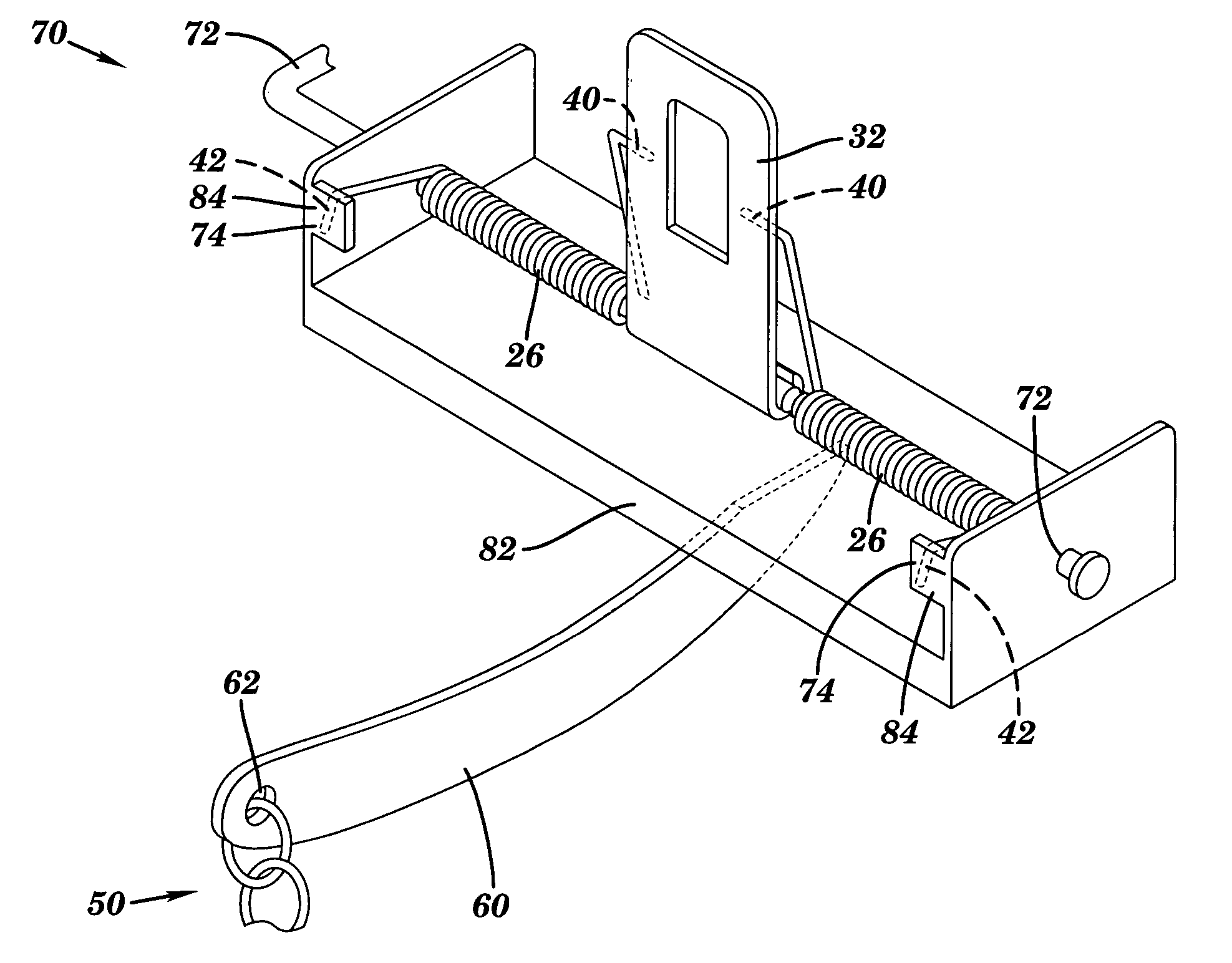
[0034] Force Applying Lever Assembly

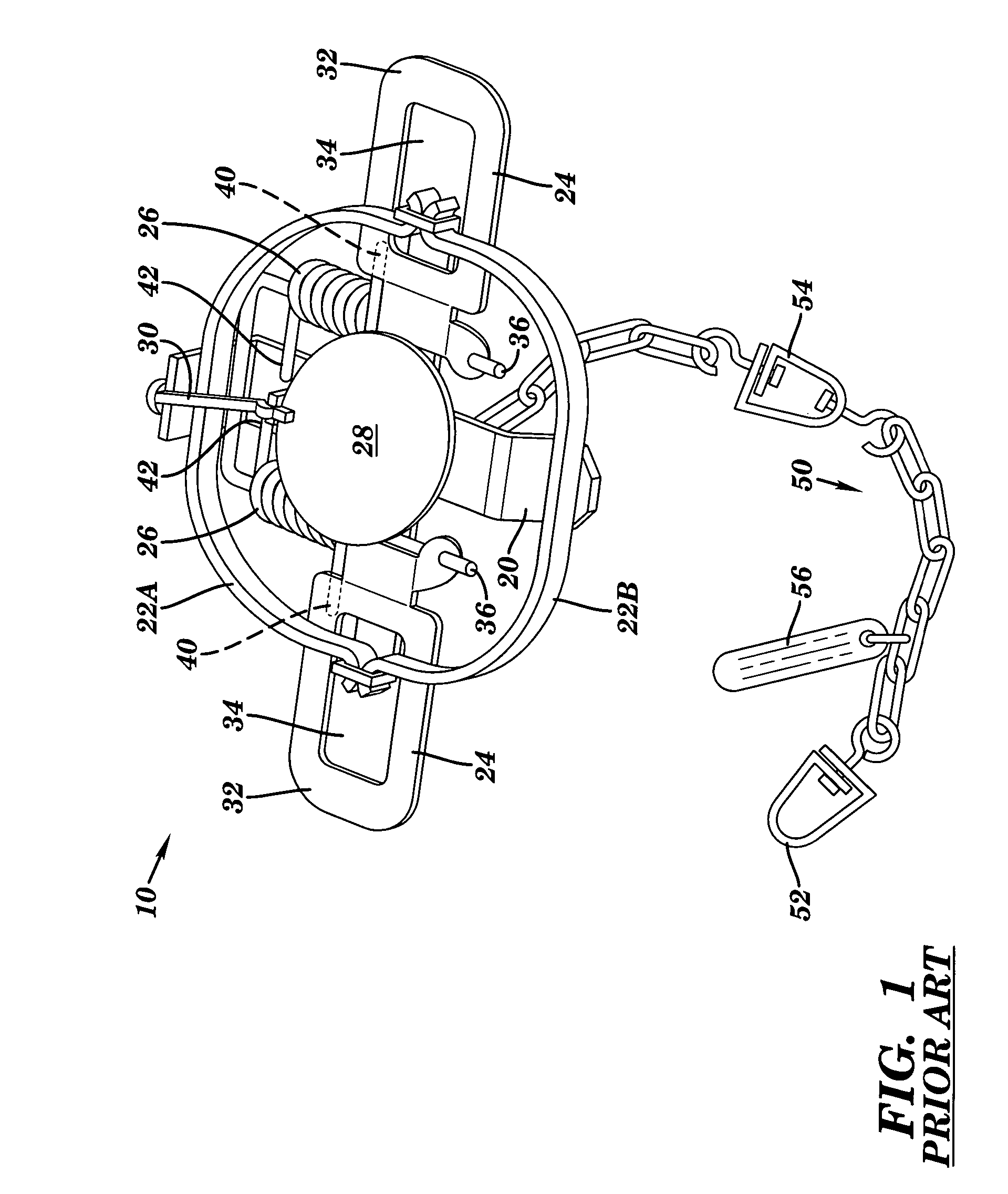
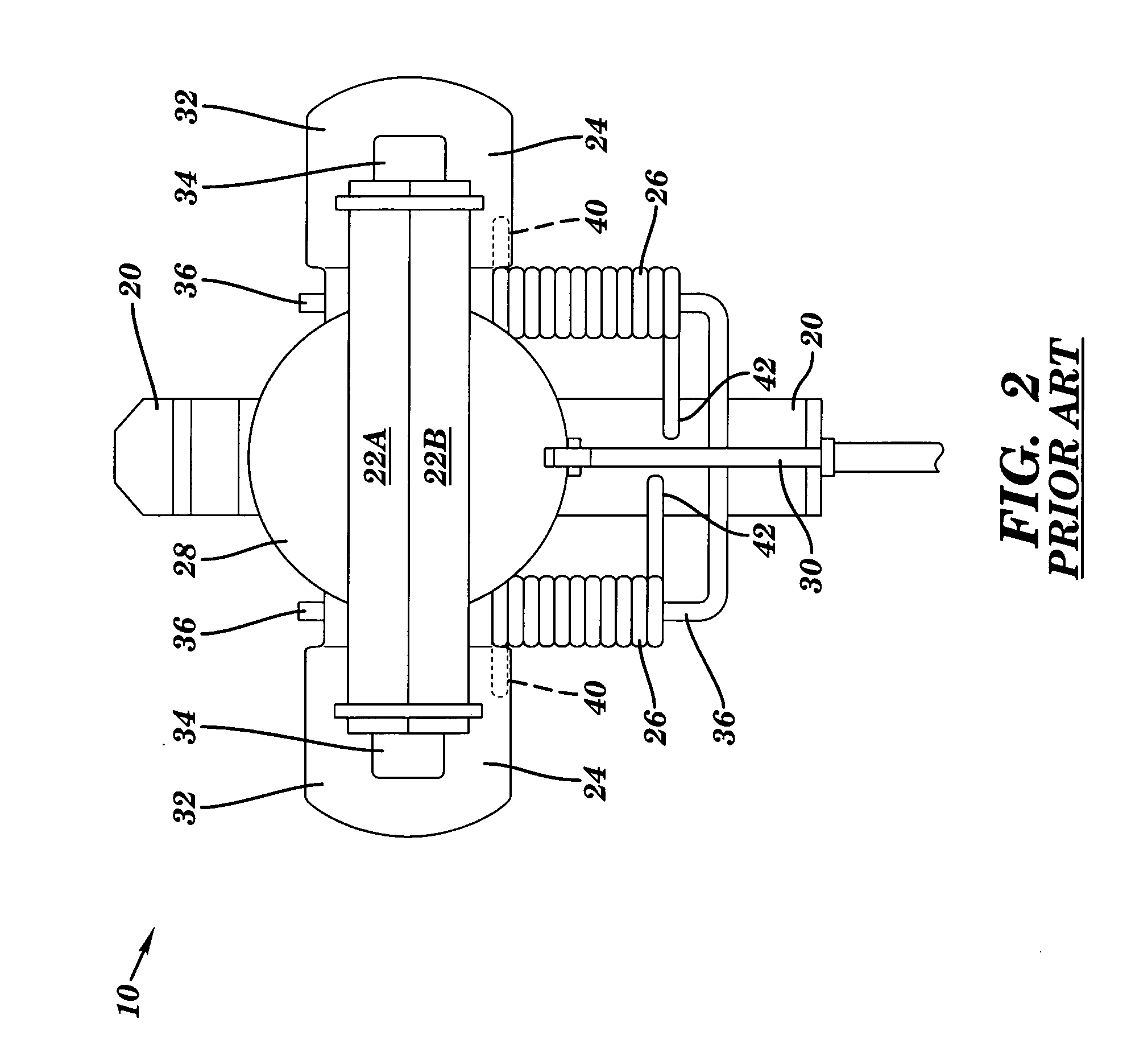
[0035]FIGS. 5 and 6 show a force applying lever assembly 70 according to the invention. Force applying lever assembly is adapted for use with trap 10 (FIGS. 1-4) for ensnaring an animal and includes a force applying lever 60 for increasing the biasing force of the trap. Force applying lever assembly 70 also has a base coupler 72 for pivotally coupling force applying lever 60 to base 20 of trap 10. Base coupler 72 may be adapted to couple using biasing device pin 36 of trap 10 (FIGS. 1-4), a screw, hinge, ball and socket, pin or any other device for pivotally coupling now known or later developed in the art. Base coupler 72 allows force applying lever 60 to pivot with respect to trap 10 as will be described in more detail below.

[0036] Force applying lever assembly 70 also has a biasing device coupler 74 for coupling force applying lever 60 to biasing device 26. Biasing device coupler 74 may include a u-shaped groove 82 as illustrated in FIG. 5, a...


PUM


Abstract

The present invention provides a force applying lever assembly for use with a foothold type trap. The force applying lever assembly has at least one force applying lever that is coupled to the biasing device or spring of the trap. The at least one force applying lever is also pivotally coupled to the base of the trap, allowing it to pivot with respect to the base. The trap's anchor, which is usually coupled to the base of the trap, is instead coupled to the end of the force applying lever opposite the base. When the ensnared animal pulls against the anchored trap, the pulling causes the force applying lever to pivot with respect to the base so as to increase the biasing force applied by the biasing device on the jaws. This additional biasing force on the jaws tightens the grip on the ensnared animal, which prevents it from escaping and discourages it from struggling. The increased biasing force in the biasing device caused by the pulling of the animal may also act as a shock absorber to prevent the animal from harming itself during the struggle. The invention also includes methods for building a trap having at least one force applying lever and for using such a trap for ensnaring an animal.

Description

BACKGROUND OF THE INVENTION [0001] 1. Technical Field [0002] The present invention relates generally to ensnaring an animal, and more particularly, to ensnaring an animal more securely without harming the animal. [0003] 2. Related Art [0004] Historically, one of the preferred ways to ensnare animals is with the use of traps. Modern traps fall into two main categories: kill-type traps and live-holding traps. Kill-type traps, such as the common mousetrap, are designed to quickly kill the captured animal, whereas live-holding traps are designed to capture the animal without killing or maiming it. Live-holding traps can be separated into box (cage-type) traps and foothold traps. [0005] The foothold trap is one of the most common forms of animal trap. Foothold traps generally have two jaws that are closed by a biasing device when an animal steps on the trigger pan. The trap is usually buried in the ground just below the surface with a light coating of dirt or ground litter. A bait or lur...

Claims


Application Information

Patent Timeline
IPC IPC(8): A01M23/26
CPCA01M23/26
Inventor BEAUREGARD, KURT D.
Owner BEAUREGARD KURT D
Why Eureka
Try Eureka