Archery sight bow mount

a bow mount and archery technology, applied in the field of archery sight bow mounts, to achieve the effect of increasing the biasing force of the spring

Inactive Publication Date: 2019-12-26
SUMMERS GREGORY E
View PDF10 Cites 0 Cited by
  • Summary
  • Abstract
  • Description
  • Claims
  • Application Information

AI Technical Summary

Benefits of technology

[0006]The first side of the mounting bracket contains an opening having a second axis normal to the first axis and which receives a screw. The screw passes through an opening in a wedge of the wedge mechanism. A knob is connected with the free end of the screw. Turning the knob in a locking direction displaces the wedge against the extension bar and the mounting bracket to lock the extension bar in the selected position. Turning the knob in a release direction opposite to the locking direction releases the wedge from the extension bar to allow movement of the extension bar relative to the mounting bracket. The wedge is preferably maintained in alignment relative to the mounting racket and extension bar by a keyway which affords displacement of the wedge along the second axis.
[0007]The mounting bracket includes a second side opposite the first side on another side of the channel. The second side contains a threaded opening having a third axis which extends normal to the first and second axes. A plunger is arranged in the second side opening for engaging a selected one of a plurality of spaced recesses in the extension bar corresponding with selected positions of the bar relative to the mounting bracket. A spring is arranged in the threaded opening and abuts against a free end of the plunger. A set screw is also arranged in the threaded opening for connection with the mounting bracket second side. Tightening the set screw increases the biasing force of the spring on the plunger to assist the plunger into a selected recess on the extension bar or against the bar in regions between the recesses. A sight connected with the extension bar, or with an elevation arm connected with the extension bar, may be positioned at a selected distance relative to the eye of the archer by displacing the bar relative to the mounting bracket and then locking the bar in the selected position.

Problems solved by technology

However, after multiple firings of the bow, vibrations between the bow mounting bracket and the extension bar ultimately twist the screw resulting in inaccuracies due to undesirable location movement of the sight pin in relation to the bow.

Method used


Image

  • Archery sight bow mount
  • Archery sight bow mount
  • Archery sight bow mount

Examples


Embodiment Construction

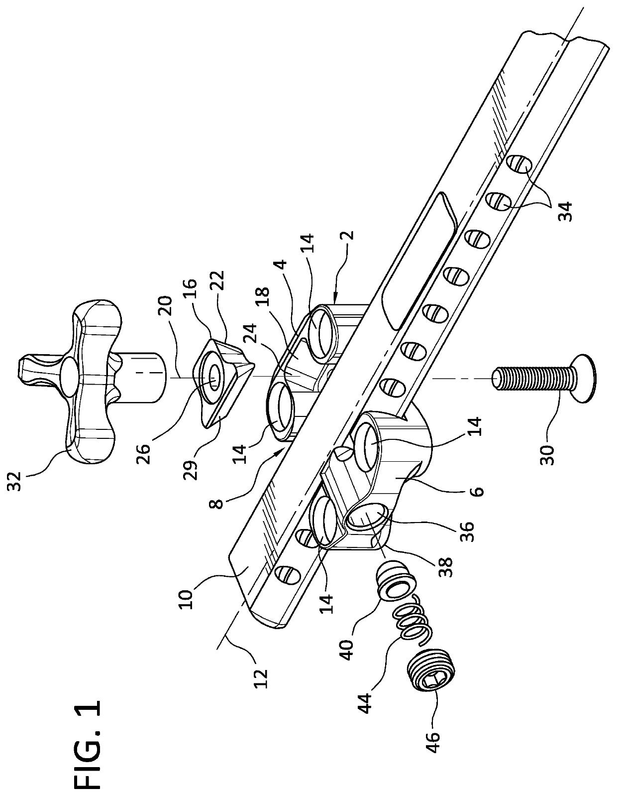
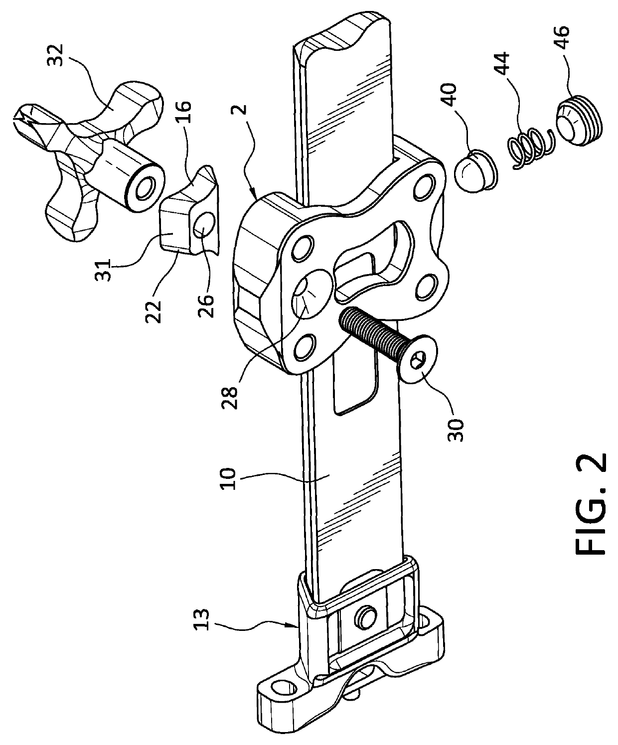
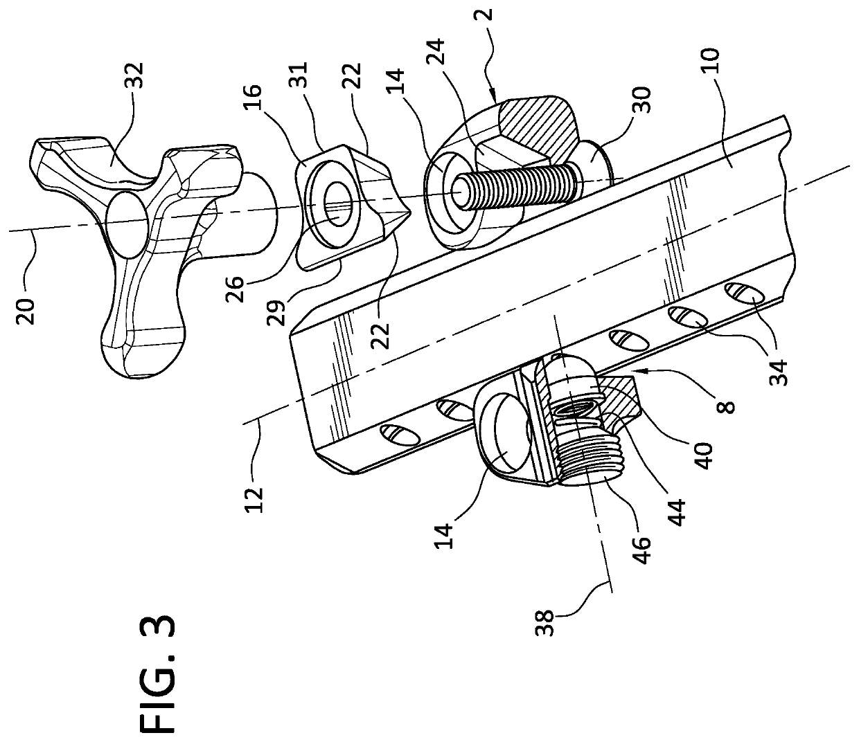
[0014]The archery sight bow mount according to the disclosure includes a mounting bracket 2 having a first side 4 and a second side 6 arranged on opposite sides of a channel 8 which is configured to receive an extension bar 10 as shown in FIGS. 1-4. In the embodiment shown, the extension bar has a dovetail configuration and extends along a first axis 12. The channel of the mounting bracket is configured to match the dovetail configuration of the extension bar so that the extension bar may be displaced relative to the mounting bracket in a first axial direction. One end of the extension bar is connected with a sight extension rail, not shown, in a conventional manner using a connection assembly 13 as shown in FIG. 2. An archery sight (not shown) is connected with the extension rail. The mounting bracket 2 includes a plurality of openings 14 which receive screws to connect the mounting bracket with a bow in a conventional manner. The mounting bracket is formed of a rigid material such...


PUM


Abstract

An archery sight bow mount includes a mounting bracket and wedge mechanism which is operable to secure a sight mounted on an extension bar in a selected position relative to the mounting bracket which is connected with a bow. The wedge mechanism includes a wedge connected with the mounting bracket and operable between locked and released positions where the wedge is tightly secured between the extension bar and the mounting bracket to lock the extension arm in the selected position and where the wedge is spaced from the extension bar to release the bar from the selected position, respectively. A setting mechanism is connected with the mounting bracket to assist with positioning the extension arm in one of many selected positions relative to the mounting bracket.

Description

BACKGROUND OF THE DISCLOSURE[0001]Archery sights are used by hunters and competition archers to increase the accuracy of a shot. The sights are typically mounted on a sight extension rail which in turn is connected with an extension bar or a sight may be attached directly to the bow. A bow mount or mounting bracket is used to connect the extension bar with a bow. The extension bar is adjustable relative to the bow mount to properly position the sight pin closer to or farther away from the archer.[0002]Archery sights normally include one or more sight pins. Improvements in sight technology have reduced or eliminated backlash of the sight pins along horizontal and vertical axes when a shot is fired. However, vibrations between the bow mounting bracket and the extension bar during firing produce sight pin location variations which decrease accuracy. That is, the sight pin fluctuates in position due to movement of the extension bar within the bow mount.[0003]The present disclosure relat...

Claims


Application Information

Patent Timeline
Patent Type & Authority Applications(United States)
IPC IPC(8): F41G1/467F41B5/14
CPCF41B5/1403F41G1/467
Inventor MASON, TRISTANSUMMERS, GREGORY E.
Owner SUMMERS GREGORY E
Why Eureka
Try Eureka