Method for extruding a workpiece with a predetermined extrusion force

A technology of extrusion force and workpiece, applied in the direction of presses, stamping machines, manufacturing tools, etc., to achieve the effects of dynamic characteristic compensation, method time optimization, and method time shortening

Active Publication Date: 2021-08-03
STIWA HLDG
View PDF5 Cites 0 Cited by
  • Summary
  • Abstract
  • Description
  • Claims
  • Application Information

AI Technical Summary

Problems solved by technology

[0004] The methods known from the prior art have the disadvantage that in order to achieve the required pressing force while observing the required tolerance range, the pressing speed must be selected correspondingly low in order to prevent the individual components of the drive train from The dynamic effect of twisting compression force due to the inertia of

Method used


Image

  • Method for extruding a workpiece with a predetermined extrusion force
  • Method for extruding a workpiece with a predetermined extrusion force
  • Method for extruding a workpiece with a predetermined extrusion force

Examples


Embodiment Construction

[0052] It should first be understood that the same reference symbols or the same component designations are used for the same parts in the different embodiments described, wherein the disclosure content contained in the entire description can be transferred to the same drawing according to the meaning Mark or the same part of the same member reference number. The positional specifications selected in the description, such as top, bottom, sideways, etc., refer to the directly described and illustrated figure and can be transferred to the new position in a meaningful way when the position is changed.

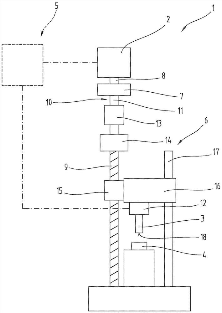
[0053] figure 1 A schematic diagram of a processing press 1 is shown. The machining press 1 comprises an electric motor 2 and a forming tool 3 coupled to the electric motor 2 . The forming tool 3 can act on a workpiece 4 in order to be able to deform it. Such deformation can be, for example, stamping. Furthermore, it is also conceivable that the workpiece 4 is bent, for exampl...


PUM


Abstract

The invention relates to a method for pressing a workpiece (4) with a predetermined pressing force by means of a forming tool (3), which is coupled to an electric motor (2) via a drive, in particular a screw drive (6), Wherein, the screw transmission mechanism (6) converts the rotational motion of the drive shaft (8) of the motor (2) into the translational motion of the forming tool (3). The method comprises the following method steps: - accelerating the motor (2) in the screw-in direction to a predetermined maximum rotational speed; - operating the motor (2) at the maximum rotational speed until the drive shaft (8) of the motor (2) has completed a predetermined number of Rotate; - reduce the speed of the motor (2) to a predetermined reduced speed; - run the motor (2) at a reduced speed until a measurement unit (12) connected downstream of the motor (2) detects that the speed exceeds the predetermined Threshold pressing force rise; - shaping of the workpiece (4) while continuously monitoring the pressing force by means of the measuring unit (12) until a predetermined pressing force is reached.

Description

technical field [0001] The invention relates to a method for pressing a workpiece with a predetermined pressing force. Background technique [0002] Various methods for pressing workpieces are known from the prior art. The methods known from the prior art relate in particular to production plants in which workpieces are to be pressed with a predetermined pressing force. In this case, the workpiece must be pressed with a predetermined pressing force, the actual value of the pressing force having only a small tolerance range. [0003] DE 19606842 A1 discloses a method for pressing a workpiece, in which a pressing rod is provided which is coupled to a drive motor via a transmission. During extrusion, the drive motor first accelerates to a maximum speed and then decelerates to a reduced speed. During operation of the drive motor at said reduced speed, the charge of the drive motor is monitored to detect the torque applied to the drive motor. [0004] The methods known from t...

Claims


Application Information

Patent Timeline
Patent Type & Authority Patents(China)
IPC IPC(8): B30B1/18B30B15/14
CPCB30B15/148B30B1/181B30B15/14B30B15/186B30B15/26
Inventor M·布伦纳T·格吕克A·戈吕恩德尔A·库吉J·麦因加斯纳M·保迪茨
Owner STIWA HLDG
Why Eureka
Try Eureka