Magneto- electronic compass error compensation method

An electronic compass and error compensation technology, applied in the directions of compass, measuring device, surveying and navigation, etc., can solve problems such as limiting measurement accuracy, and achieve the effect of high-precision measurement

Inactive Publication Date: 2010-06-09
UNIV OF SCI & TECH BEIJING
View PDF6 Cites 3 Cited by
  • Summary
  • Abstract
  • Description
  • Claims
  • Application Information

AI Technical Summary

Problems solved by technology

The above compensation algorithm assumes that the distribution of the horizontal projection component of the magnetic field intensity is a regular ellipse, but in fact, due to the complexity of the specific situation, it is difficult to ensure the strict establishment of this condition, thus limiting the improvement of measurement accuracy

Method used


Image

  • Magneto- electronic compass error compensation method
  • Magneto- electronic compass error compensation method
  • Magneto- electronic compass error compensation method

Examples


Embodiment Construction

[0020] A specific example of using the patent of the present invention to realize the error compensation of the magneto-electronic compass is given below.

[0021] In this example, a high-performance three-axis magnetoresistance sensor is used as a geomagnetic azimuth sensor to measure the components of the geomagnetic field on the x-axis, y-axis, and z-axis of the carrier. A dual-axis acceleration sensor is used to measure the pitch angle (θ) and roll angle (γ). Combining the information of the above multiple sensors to achieve high-precision measurement of the geomagnetic azimuth

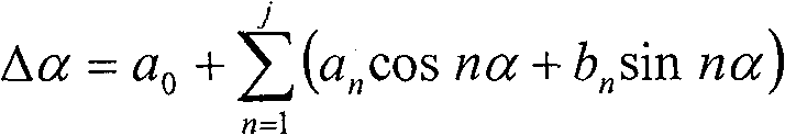
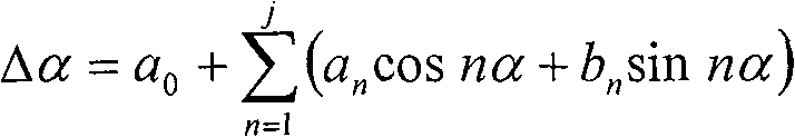
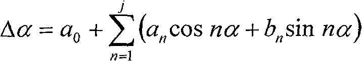
[0022] The realization of the magnetic electronic compass error compensation method proposed by the patent of the present invention is divided into two stages, namely the coefficient calculation stage of the calibration process and the error compensation stage of the use process. In the calibration process, the compensation formula coefficient is calculated according to the measured error value; in th...


PUM


Abstract

The invention provides an electronic magnetic compass error compensation method which bases on deformation round distribution and cyclical assumptions. The measurement error caused by around ferromagnetic materials and other factors must be compensated to enhance electronic magnetic compass measurement accuracy. At present, domestic and foreign popular methods of compensation are based on assumptions which relate to the effect of the environmental interference magnetic field causing the magnetic field strength level projection component distribution from round into oval. But because of more and complicated influence factors, in fact the magnetic field strength level projection component distribution can not be guarantee as perfect oval. In view of this situation, the invention provides error compensation algorithmic method which bases on deformation round distribution and cyclical assumptions, the objective is to compensate the measurement error caused by around ferromagnetic materialsand other factors, and achieve magnetic azimuth high-precision measurement.

Description

Technical field [0001] The patent of the invention relates to a magneto-electronic compass that uses the earth's magnetic field to realize the orientation function, and provides a method for compensating the measurement error of the magneto-electronic compass. Background technique [0002] When the magnetic electronic compass is fixed on the carrier, the measurement result of the geomagnetic azimuth will be affected by the surrounding ferromagnetic material. The interference magnetic field is composed of hard iron magnetic field and soft iron magnetic field. When there is an interference magnetic field around, the distribution of the horizontal projection component of the magnetic field strength is no longer a perfect circle, its shape is distorted (the influence of the soft iron magnetic field), and its center position is also offset from the origin of the coordinate (the hard iron magnetic field) influences). The existence of the above factors leads to measurement errors of t...

Claims


Application Information

Patent Timeline
Patent Type & Authority Patents(China)
IPC IPC(8): G01C17/38G01C17/30
Inventor 李希胜王磊舒雄鹰王立锦
Owner UNIV OF SCI & TECH BEIJING
Why Eureka
Try Eureka