
Non-contact type overvoltage sensor based on electro-optic effect

A non-contact, electro-optical effect technology, applied in the measurement of current/voltage, voltage/current isolation, instruments, etc., can solve problems such as unstable operation, power grid failure, deviation, etc.

Inactive Publication Date: 2014-08-06
CHONGQING UNIV
View PDF8 Cites 16 Cited by
  • Summary
  • Abstract
  • Description
  • Claims
  • Application Information

AI Technical Summary

Problems solved by technology

These sensors based on the electro-optical effect have the characteristics of small size, high response frequency, and low electromagnetic interference, but their important disadvantage is that they are all in contact with the primary equipment of the power system, which deviates from the safe operation of the power grid, and their own unstable operation may Instead, it causes the failure of the entire grid

Method used


Image

  • Non-contact type overvoltage sensor based on electro-optic effect
  • Non-contact type overvoltage sensor based on electro-optic effect
  • Non-contact type overvoltage sensor based on electro-optic effect

Examples


Embodiment Construction

[0021] The present invention will be described in detail below in conjunction with the accompanying drawings.

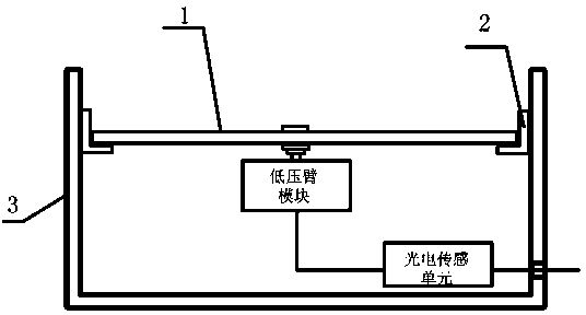
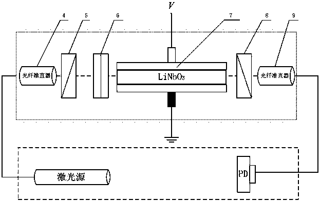
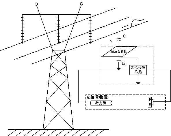
[0022] see Figure 1-3 , a non-contact overvoltage sensor based on the electro-optical effect, including a metal shielding shell, a non-contact sensing unit and a photoelectric sensing unit;

[0023] The non-contact sensing unit includes an induction metal plate 1, a low-voltage arm module and a coaxial cable. The induction metal plate is used to be arranged under the overhead transmission line, and the low-voltage arm module low-voltage arm is arranged between the induction metal plate and the ground. , the other end of the low-voltage arm module is electrically connected to the signal input end of the photoelectric sensing unit through a coaxial cable, and the photoelectric sensing unit is used to convert the voltage signal output by the low-voltage arm module into an optical signal.

[0024] The induction metal plate 1 is set in the metal shielding shell 3 throug...


PUM


Abstract

The invention discloses a non-contact type overvoltage sensor based on the electro-optic effect. The non-contact type overvoltage sensor comprises a non-contact sensing unit and an electro-optic sensing unit, wherein the non-contact sensing unit comprises an induction metal plate and a low-voltage arm module, the induction metal plate is used for being arranged below an aerial power transmission line, the low-voltage arm module is arranged between the induction metal plate and the ground, the low-voltage arm module is composed of a capacitor C2 and a peripheral circuit of the capacitor C2, one end of the capacitor C2 of the low-voltage arm module is electrically connected with the induction metal plate, the other end of the capacitor C2 is grounded, and a voltage signal output end between the capacitor C2 and the induction metal plate is electrically connected with a signal input end of the electro-optic sensing unit. The non-contact type overvoltage sensor based on the electro-optic effect is simple in structure, small in size, high in stability, and convenient to install, popularize and apply, and facilitates remote control; mutual conversion between optical signals and electrical signals is achieved through the electro-optic effect, long-distance signal transmission is achieved through optical fibers, and compared with a traditional photoelectric sensor, the non-contact type overvoltage sensor based on the electro-optic effect has the advantages that the size is smaller, the response efficiency is higher, and the sensor is not influenced by an electromagnetic field.

Description

technical field [0001] The invention belongs to the technical field of voltage monitoring of high-voltage transmission lines, and in particular relates to a non-contact overvoltage sensor. Background technique [0002] With the increase of the capacity of my country's power grid, users have put forward higher requirements for the safe and reliable operation of the power system. Operation experience shows that the amplitude of overvoltage in the ultra-high voltage power grid is relatively high, which seriously causes serious damage to the insulation structure of substations and transmission lines. threaten. The substation is the hub of the power system, and most of the internal insulation of the main electrical equipment such as transformers in the substation has no self-recovery ability. Once it is damaged due to lightning overvoltage or operating overvoltage, it is very difficult to repair and may bring serious consequences. Therefore, overvoltage protection has always been...

Claims


Application Information

Patent Timeline
IPC IPC(8): G01R15/24G01R19/165
Inventor 杨庆韩睿司马文霞袁涛杜林董恒孙尚鹏刘通
Owner CHONGQING UNIV
Learn More