An ophthalmic vision test table

A vision test and ophthalmology technology, applied in the field of test tables, can solve problems such as poor test results and identification errors

Inactive Publication Date: 2019-01-15
王哲
View PDF9 Cites 3 Cited by
  • Summary
  • Abstract
  • Description
  • Claims
  • Application Information

AI Technical Summary

Problems solved by technology

[0003] In order to overcome the disadvantages that patients with low vision may not be able to see clearly which symbol the medical staff is pointing to with a stick, resulting in misidentification and poor test results, the technical problem of the present invention is to provide a Ophthalmology vision test chart with symbols and good test results

Method used


Image

  • An ophthalmic vision test table
  • An ophthalmic vision test table

Examples


Embodiment 1

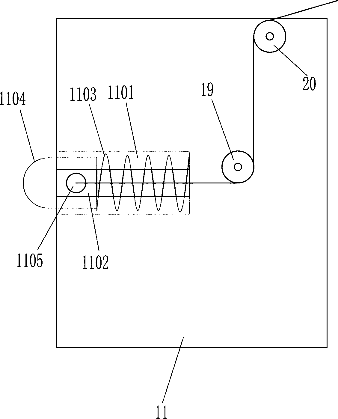
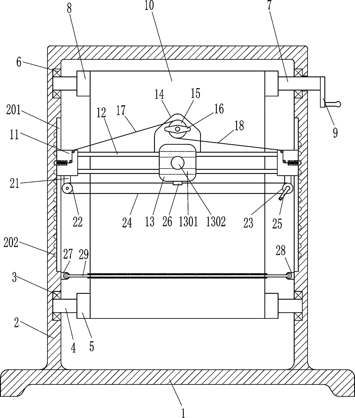
[0018] An ophthalmic vision test chart, such as Figure 1-2 As shown, it includes a bottom bracket 1, a U-shaped bracket 2, a first bearing 3, a first shaft 4, a first reel 5, a second bearing 6, a second shaft 7, a second reel 8, and a first rocker arm 9. Eye chart 10, slide block 11, spring 1103, block 1104, driving lever 1105, guide rod 12 and guide plate 13, the top of bottom bracket 1 is connected with U-shaped bracket 2, and the left and right sides in U-shaped bracket 2 are all Have a chute 201, the left wall of the left chute 201 and the right wall of the right chute 201 are evenly provided with a plurality of grooves 202, the lower parts of the left and right sides of the U-shaped bracket 2 are equipped with the first bearing 3, the first The inner interference of the bearing 3 is connected with the first shaft 4, the first shaft 4 is connected with the first reel 5, and the tops of the left and right sides of the U-shaped bracket 2 are installed with the second beari...

Embodiment 2

[0020] An ophthalmic vision test chart, such as Figure 1-2 As shown, it includes a bottom bracket 1, a U-shaped bracket 2, a first bearing 3, a first shaft 4, a first reel 5, a second bearing 6, a second shaft 7, a second reel 8, and a first rocker arm 9. Eye chart 10, slide block 11, spring 1103, block 1104, driving lever 1105, guide rod 12 and guide plate 13, the top of bottom bracket 1 is connected with U-shaped bracket 2, and the left and right sides in U-shaped bracket 2 are all Have a chute 201, the left wall of the left chute 201 and the right wall of the right chute 201 are evenly provided with a plurality of grooves 202, the lower parts of the left and right sides of the U-shaped bracket 2 are equipped with the first bearing 3, the first The inner interference of the bearing 3 is connected with the first shaft 4, the first shaft 4 is connected with the first reel 5, and the tops of the left and right sides of the U-shaped bracket 2 are installed with the second beari...

Embodiment 3

[0023] An ophthalmic vision test chart, such as Figure 1-2 As shown, it includes a bottom bracket 1, a U-shaped bracket 2, a first bearing 3, a first shaft 4, a first reel 5, a second bearing 6, a second shaft 7, a second reel 8, and a first rocker arm 9. Eye chart 10, slide block 11, spring 1103, block 1104, driving lever 1105, guide rod 12 and guide plate 13, the top of bottom bracket 1 is connected with U-shaped bracket 2, and the left and right sides in U-shaped bracket 2 are all Have a chute 201, the left wall of the left chute 201 and the right wall of the right chute 201 are evenly provided with a plurality of grooves 202, the lower parts of the left and right sides of the U-shaped bracket 2 are equipped with the first bearing 3, the first The inner interference of the bearing 3 is connected with the first shaft 4, the first shaft 4 is connected with the first reel 5, and the tops of the left and right sides of the U-shaped bracket 2 are installed with the second beari...


PUM


Abstract

The invention relates to a test table, in particular to an ophthalmic vision test table. Therefore, the technical problem of the present invention is to provide an ophthalmic vision test table that enables a patient to see the symbol clearly and has a good test effect. The technical embodiment of the invention is as follows: an ophthalmic visual acuity test table comprises a bottom bracket, a U-shaped bracket, a first bearing, a first shaft, a first reel, a second bearing, a second shaft, a second reel, a first rocker arm, a visual acuity chart and the like. The top of the bottom bracket is connected with a U-shaped bracket, the left and right sides of the U-shaped bracket are provided with sliding grooves, the left side sliding groove left wall and the right side sliding groove right wallare uniformly provided with a plurality of grooves, and the lower parts of the left and right sides of the U-shaped bracket are provided with first bearings. A medical staff grasp that first rocker arm and rotate or reverse the second shaft rod, and the second shaft rod rotates or reverse to drive the second reel to rotate or reverse, thereby driving the visual acuity chart to rotate, so that symbols seen by the patient from the t hole are different in size, and the eyesight of the patient is tested.

Description

technical field [0001] The invention relates to a test table, in particular to an ophthalmology vision test table. Background technique [0002] When people feel poor eyesight, they usually go to the hospital for a vision test. Now hospitals generally use eye charts to test patients’ vision. Patient identification is used to test the patient's vision. However, the patient with low vision may not be able to see which symbol the medical staff is pointing at with the stick, leading to identification errors and poor test results. Contents of the invention [0003] In order to overcome the disadvantages that patients with low vision may not be able to see clearly which symbol the medical staff is pointing to with a stick, resulting in misidentification and poor test results, the technical problem of the present invention is to provide a Ophthalmic vision test chart with symbols and good test results. [0004] The technical embodiment of the present invention is: an ophthalmic...

Claims


Application Information

Patent Timeline
Patent Type & Authority Applications(China)
IPC IPC(8): A61B3/032
CPCA61B3/0075A61B3/032
Inventor 谢彩燕
Owner 王哲
Why Eureka
Try Eureka