
A speed limiting device for a railway train and a method for using the device

A speed limit, train technology, applied in railway car body parts, railway braking systems, brakes where braking elements interact with rails, etc., can solve the problems of unsuitable reduction gears, damage to reduction gears, and weakened deceleration effects. Achieve the effect of increasing reliability, speeding up deceleration and improving service life

Inactive Publication Date: 2019-01-15
宁波仓央电子科技有限公司
View PDF0 Cites 6 Cited by
  • Summary
  • Abstract
  • Description
  • Claims
  • Application Information

AI Technical Summary

Problems solved by technology

[0002] In order to prevent the derailment caused by the train speed too fast, it is necessary to maintain the speed of the train within a certain speed. Because the inertia of the train is too large, the ordinary deceleration device is not suitable for the train, and the deceleration process of the train is often a comparison. It is a long process. The existing deceleration device weakens the deceleration effect under long-term braking friction, and the deceleration device is damaged due to excessive speed during the deceleration process. This equipment effectively solves this problem

Method used


Image

  • A speed limiting device for a railway train and a method for using the device
  • A speed limiting device for a railway train and a method for using the device
  • A speed limiting device for a railway train and a method for using the device

Examples


Embodiment Construction

[0019] All features disclosed in this specification, or steps in all methods or processes disclosed, may be combined in any manner, except for mutually exclusive features and / or steps.

[0020] Any feature disclosed in this specification (including any appended claims, abstract and drawings), unless expressly stated otherwise, may be replaced by alternative features which are equivalent or serve a similar purpose. That is, unless expressly stated otherwise, each feature is one example only of a series of equivalent or similar features.

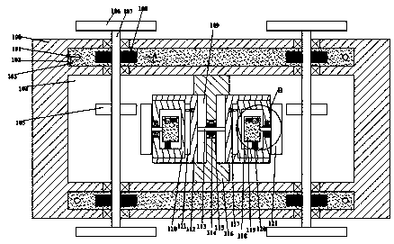
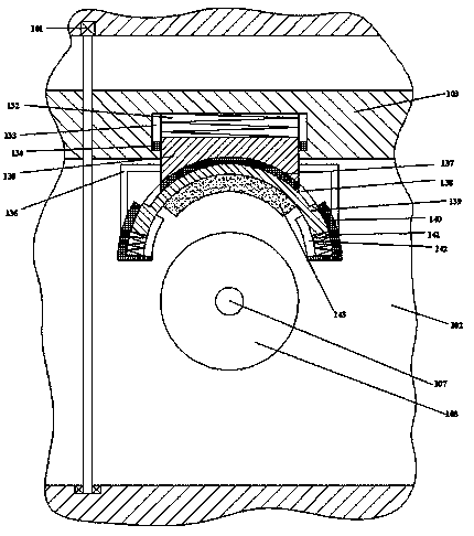
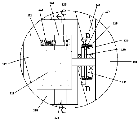
[0021] Such as Figure 1-5 As shown, for the convenience of description, the orientations mentioned below are stipulated as follows: the directions of up, down, left, right, front, back and figure 1The up, down, left, right, front and back directions of the projection relationship are consistent. A railway train speed limiting device and its use method of the present invention include several driving platforms 100 fixed under the train, and a...


PUM


Abstract

The invention discloses a speed limiting device for a railway train and a method for using the device. The device comprises a plurality of platforms fixed under the train. A medium speed reduction chamber is fixedly arranged in that travel platform. The front and rear sides of the medium speed reduction chamber are provided with front and rear symmetrical side speed reduction chambers. A left-right symmetrical travel shaft is arranged in that rotating medium speed reduction chamber. The device is simple in structure and convenient to use, and adopts multiple-channel speed reduction devices which work at the same time to slow the train down and to increase the train speed reduction rate. When the speed of the train is too high, buffer and switching equipment is added into the speed reduction device, so that the speed reduction device can be effectively protected from being worn or even damaged without reducing the efficiency of the train speed reduction, the service life of the speed reduction device is effectively prolonged, and the reliability of the speed reduction device is also increased.

Description

technical field [0001] The invention relates to the field of trains, in particular to a speed limiting device for railway trains and a method for using the same. Background technique [0002] In order to prevent the derailment caused by the train speed too fast, it is necessary to maintain the speed of the train within a certain speed. Because the inertia of the train is too large, the ordinary deceleration device is not suitable for the train, and the deceleration process of the train is often a comparison. In the long process, the existing deceleration device weakens the deceleration effect under long-term braking friction, and the deceleration device is damaged due to excessive speed during the deceleration process. This equipment effectively solves this problem. Contents of the invention [0003] The object of the present invention is to provide a railway train speed limiting device and its use method, which can overcome the above-mentioned defects of the prior art. ...

Claims


Application Information

Patent Timeline
Patent Type & Authority Applications(China)
IPC IPC(8): B61H11/14B61H7/12
CPCB61H11/14B61H7/12
Inventor 韩方佳
Owner 宁波仓央电子科技有限公司
Learn More