Liquid crystal lens, stereoscopic display device, and intelligent terminal

A technology of liquid crystal lens and liquid crystal layer, applied in static indicators, optics, instruments, etc., can solve the problems of large spacing between first liquid crystal lens units, large sawtooth, affecting viewing experience, etc., so as to improve user experience and weaken the sawtooth phenomenon. Effect

Inactive Publication Date: 2019-01-15
SUPERD CO LTD
View PDF0 Cites 4 Cited by
  • Summary
  • Abstract
  • Description
  • Claims
  • Application Information

AI Technical Summary

Problems solved by technology

[0002] The three-dimensional display device includes a liquid crystal lens and a display panel that are arranged oppositely. The liquid crystal lens splits light on the three-dimensional image provided by the display panel to form a three-dimensional display effect. However, the driving electrodes placed obliquely will bring another interference factor that affects the viewing experience. Specifically, in the light splitting mode of the liquid crystal lens, the extension direction of the first liquid crystal lens unit arranged in an array is different from the direction of the display pixels in the display panel. There is a certain included angle in the arrangement direction, and in order to meet the needs of imaging and light splitting, the distance between the first liquid crystal lens units is relatively large, resulting in the refraction of the light emitted by the display panel through the first liquid crystal lens units, and the angle of refraction is relatively large, causing the viewer to When viewing a stereoscopic display device, there are large jaggies on the edge of the liquid crystal lens, which affects the viewing experience

Method used


Image

  • Liquid crystal lens, stereoscopic display device, and intelligent terminal
  • Liquid crystal lens, stereoscopic display device, and intelligent terminal
  • Liquid crystal lens, stereoscopic display device, and intelligent terminal

Examples


Embodiment Construction

[0029] In order to make the object, technical solution and advantages of the present invention clearer, various embodiments of the present invention will be described in detail below in conjunction with the accompanying drawings. However, those of ordinary skill in the art can understand that, in each implementation manner of the present invention, many technical details are provided for readers to better understand the present application. However, even without these technical details and various changes and modifications based on the following implementation modes, the technical solution claimed in this application can also be realized.

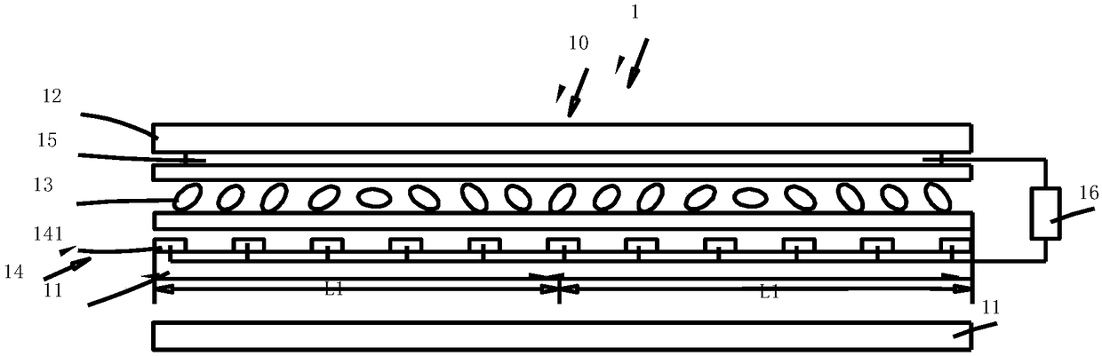
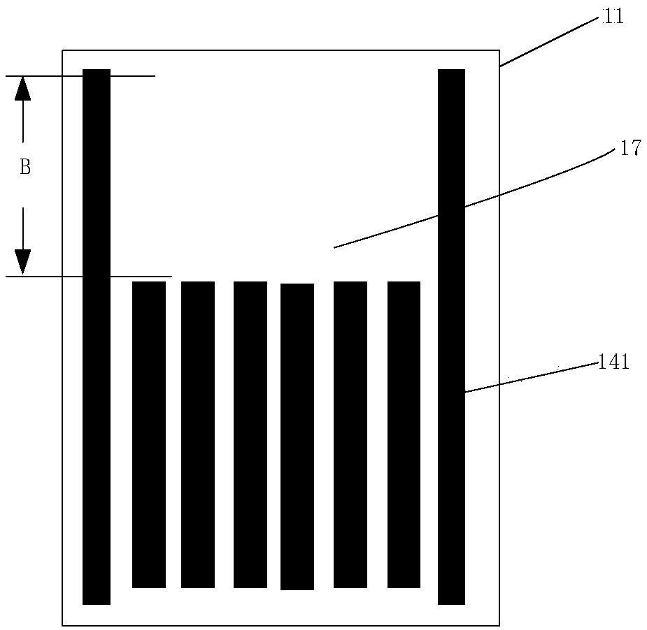
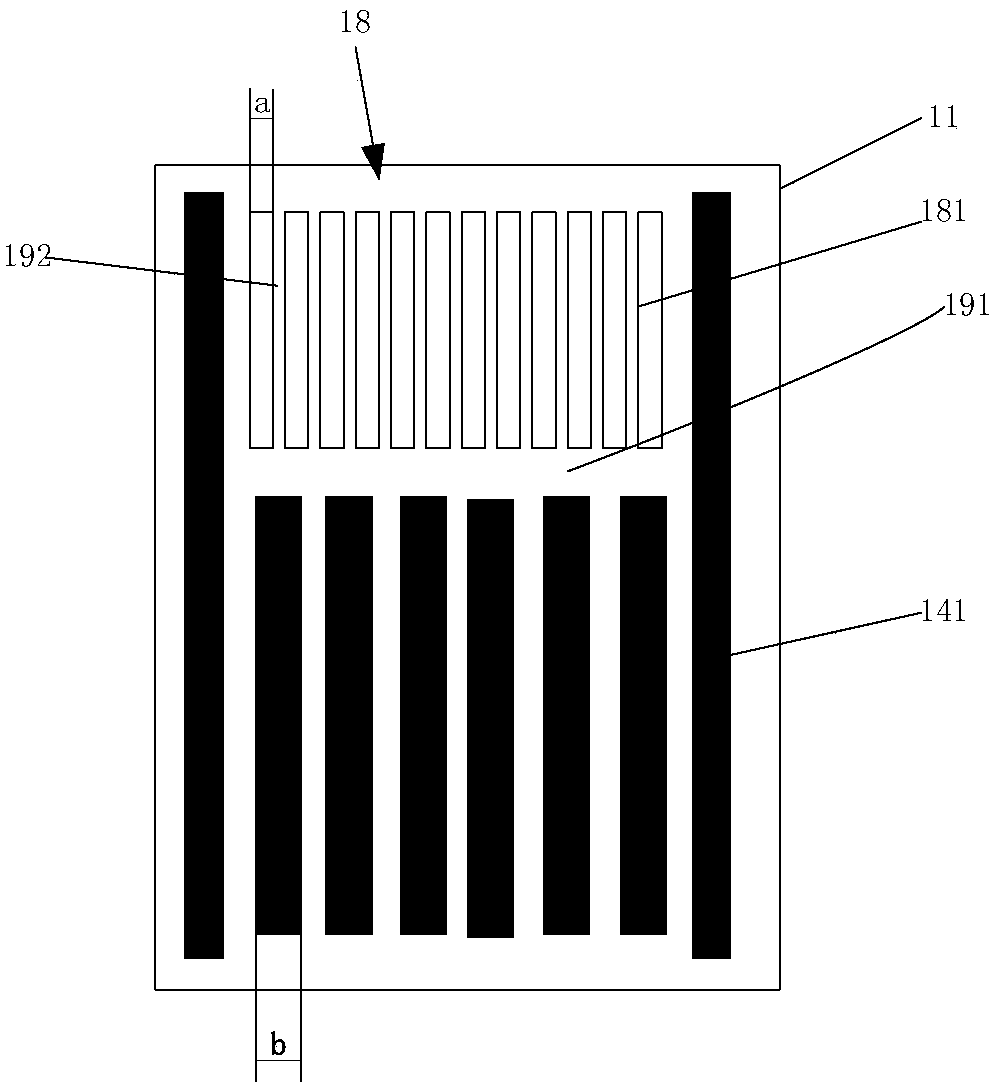
[0030] The pitch of the liquid crystal lens unit proposed in this embodiment refers to the distance between the centerlines of the two electrodes located at the edge of the liquid crystal lens unit.

[0031] Such as Figure 1 to Figure 3 As shown, the stereoscopic display device 1 provided by the embodiment of the present invention include...


PUM

PropertyMeasurementUnit
widthaaaaaaaaaa
widthaaaaaaaaaa

Abstract

The invention relates to the technical field of stereoscopic display, and discloses a liquid crystal lens, a stereoscopic display device, and an intelligent terminal. The liquid crystal lens comprisesa first substrate and a second substrate arranged in an opposite manner, and a liquid crystal layer arranged between the first substrate and the second substrate, the first substrate is provided witha first electrode layer, the first electrode layer comprises a plurality of first bar-shaped electrodes arranged at intervals, the second substrate is provided with a second electrode layer, the second electrode layer comprises a common electrode, and micro-electrode structures are arranged between two adjacent first bar-shaped electrodes at edges of the first electrode layer. When the liquid crystal lens is in a light-splitting mode, a voltage driver respectively applies a first driving voltage and a second driving voltage to the first bar-shaped electrodes and the micro-electrode structuresand applies a second voltage to the common electrode, and the deflection of liquid crystal molecules is driven to respectively form first liquid crystal lens units and second liquid crystal lens units arranged in an array manner near the first bar-shaped electrodes and the micro-electrode structures so that jaggies at edges of the liquid crystal lens can be effectively weakened or even eliminated, and the user experience is enhanced.

Description

technical field [0001] The invention relates to the technical field of stereoscopic display, in particular to a liquid crystal lens, a stereoscopic display device and an intelligent terminal. Background technique [0002] The three-dimensional display device includes a liquid crystal lens and a display panel that are arranged oppositely. The liquid crystal lens splits light on the three-dimensional image provided by the display panel to form a three-dimensional display effect. However, the driving electrodes placed obliquely will bring another interference factor that affects the viewing experience. Specifically, in the light splitting mode of the liquid crystal lens, the extension direction of the first liquid crystal lens unit arranged in an array is different from the direction of the display pixels in the display panel. There is a certain included angle in the arrangement direction, and in order to meet the needs of imaging and light splitting, the distance between the f...

Claims


Application Information

Patent Timeline
Patent Type & Authority Applications(China)
IPC IPC(8): G02F1/29G02F1/1343G02F1/133G02B27/22
CPCG02B30/27G02F1/13306G02F1/134309G02F1/29
Inventor 王红磊宫晓达
Owner SUPERD CO LTD
Why Eureka
Try Eureka