
mouse device

A device and mouse technology, which is applied in the fields of instruments, calculations, electrical digital data processing, etc., can solve problems such as the easy breakage of the elastic arm and the difficulty in forming the structure of the elastic arm, so as to achieve the effect of improving operational functionality and prolonging the service life

Active Publication Date: 2021-12-07
DARFON ELECTRONICS (SUZHOU) CO LTD +1
View PDF6 Cites 0 Cited by
  • Summary
  • Abstract
  • Description
  • Claims
  • Application Information

AI Technical Summary

Problems solved by technology

[0003] However, since the above-mentioned roller seat and the mouse base are only connected by an integrally formed slender elastic arm, the above-mentioned design usually has the disadvantages that the elastic arm structure is not easy to form and the elastic arm is prone to breakage after a period of repeated deflection and deformation. The problem

Method used


Image

  • mouse device
  • mouse device
  • mouse device

Examples


Embodiment Construction

[0026] The following descriptions of the various embodiments refer to the accompanying drawings to illustrate specific embodiments in which the present invention can be practiced. The directional terms mentioned in the present invention, such as "upper", "lower", "front", "rear", "left", "right", "side", etc., are only referring to the directions of the attached drawings. Therefore, the directional terms used are used to illustrate and understand the present invention, but not to limit the present invention.

[0027] In the following embodiments, the same parts are denoted by the same symbols in different drawings.

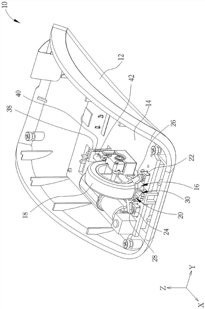
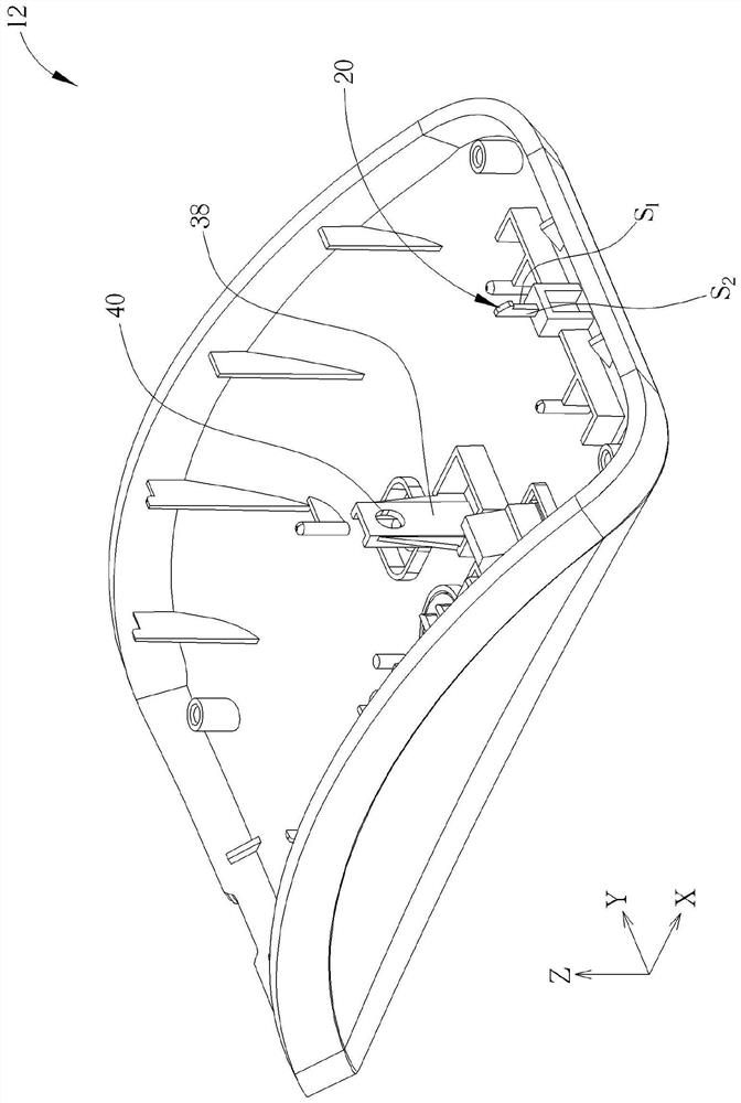
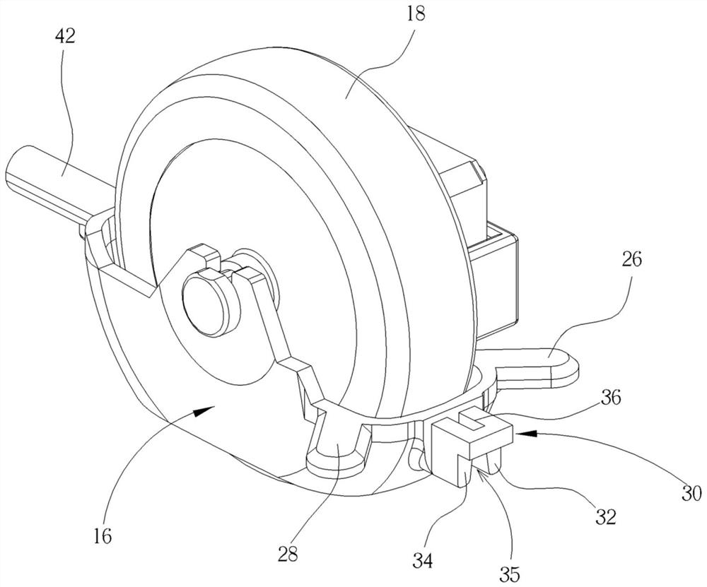
[0028] see figure 1 , figure 2 as well as image 3 , figure 1 It is a three-dimensional schematic diagram of a mouse device 10 proposed according to an embodiment of the present invention, figure 2 for figure 1 An enlarged schematic view of the base 12, image 3 for figure 1 The enlarged schematic view of the swing seat 16 and the scroll wheel 18, wherei...


PUM


Abstract

The invention discloses a mouse device comprising a base, a circuit board arranged on the base and having a micro switch, a swing base having a trigger arm and a forward bending arm, and a roller. The base has an upright hook protruding along the Z axis. The trigger arm is extended towards the micro switch, and the forward bending arm has a slot end and a first and a second side which are inclined outward from the two sides of the slot end along the Z-axis to the base to form a horn-shaped limiting space. On the two side arms, the upright hooks pass through the horn-shaped limiting space and are hooked to the ends of the slot holes so that the swing seat is deflectably arranged on the base relative to the X axis. The roller is rotatably arranged on the swing seat relative to the Y axis. When the roller is forced laterally to drive the oscillating seat to deflect toward the microswitch, the trigger arm is biased to trigger the microswitch, and the first side arm part laterally abuts against the first side of the upright hook.

Description

technical field [0001] The invention relates to a mouse device, in particular to a mouse device in which a swing seat is deflectably engaged on a base. Background technique [0002] In the current mouse design, in order to improve the operation functionality of the mouse, in addition to using the mouse wheel to perform forward and backward rotation operations (such as controlling the vertical scroll bar of the window operation interface to move up and down) and pressing the trigger operation, it can be further configured There is a scroll wheel bias function to allow the user to complete the corresponding axial operation (such as controlling the horizontal scroll bar of the window operation interface to move left and right) by biasing the scroll wheel sideways with the finger. The common structural design is based on the slender elastic arm The mouse base is connected with the roller seat for accommodating the roller, whereby the roller seat can be arranged on the mouse base...

Claims


Application Information

Patent Timeline
Patent Type & Authority Patents(China)
IPC IPC(8): G06F3/0354
CPCG06F3/03543
Inventor 萧绍仑
Owner DARFON ELECTRONICS (SUZHOU) CO LTD
Learn More