
Multifunctional push knob

a multi-functional, push-knob technology, applied in the direction of mechanical control devices, instruments, controlling members, etc., can solve the problems of inability to integrate multiple functions, limited application, and only output one signal of the switch, so as to improve the operation functionality and flexibility, and reduce the space. , the effect of high-integration control devices

Active Publication Date: 2020-10-13
CHU CHING HSIUNG
View PDF9 Cites 3 Cited by
  • Summary
  • Abstract
  • Description
  • Claims
  • Application Information

AI Technical Summary

Benefits of technology

The present invention provides a device with a rotating frame that can be limited in its rotation range. This limitation can be achieved by the device's base and main rotation frame both having rotation limited elements. This device can be used as an operation switch for various equipment in a car. It can improve operational functionality and flexibility and allow for various controls in the car. Additionally, the device's interface can reduce space, which is not always obvious with conventional technology.

Problems solved by technology

Although both of them have their application advantages, a switch usually only outputs one signal and its application is also limited.
In terms of integrated applications, if only a single switch device is used to achieve functions that include displaying menus, switching menus, selecting function items, determining function items, etc., and achieve the integration of multiple functions, it is almost impossible.
It's a bottleneck in the existing technology.

Method used

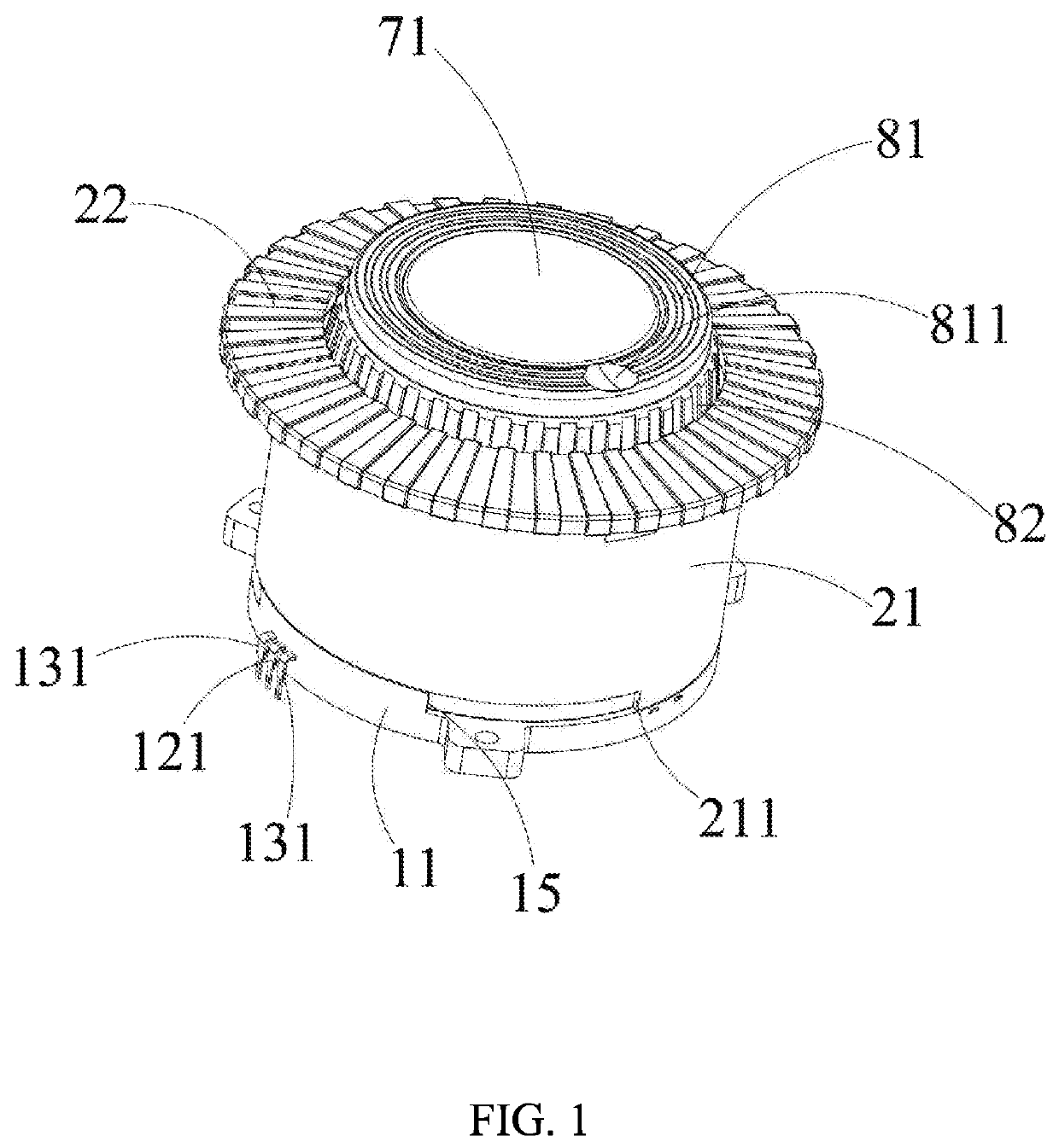
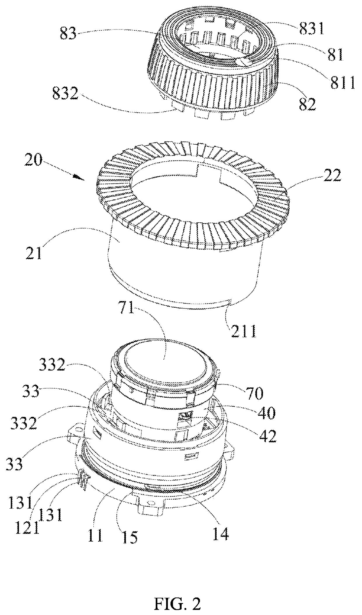
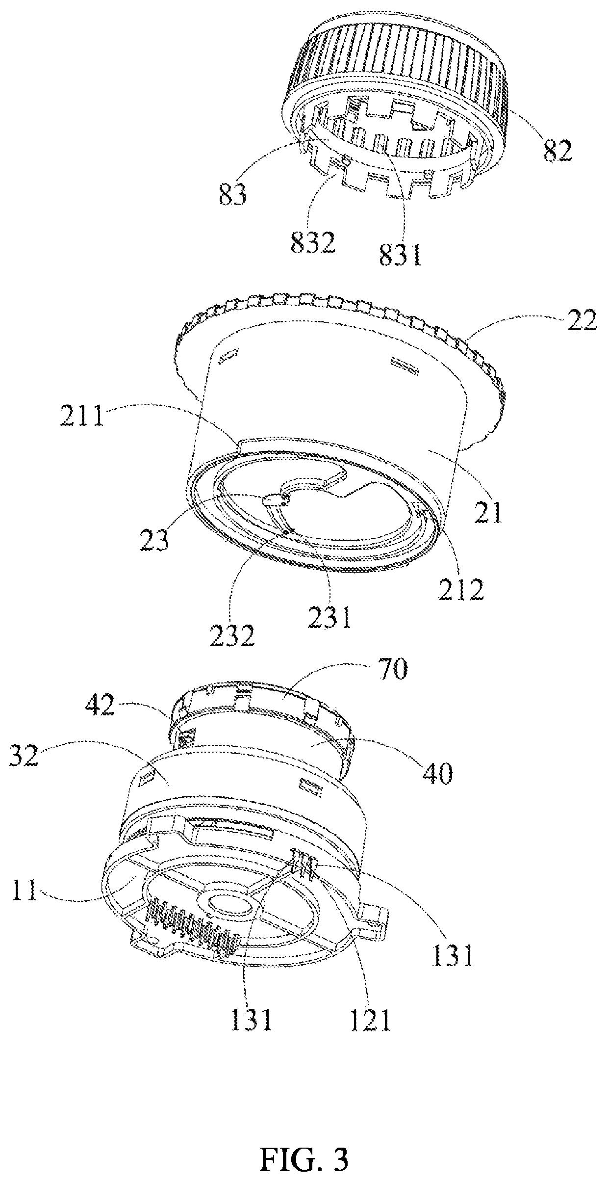

Image

  • Multifunctional push knob
  • Multifunctional push knob
  • Multifunctional push knob

Examples


Embodiment Construction

[0024]Reference will now be made in detail to the exemplary embodiments of the present invention, examples of which are illustrated in the accompanying drawings. Therefore, it is to be understood that the foregoing is illustrative of exemplary embodiments and is not to be construed as limited to the specific embodiments disclosed, and that modifications to the disclosed exemplary embodiments, as well as other exemplary embodiments, are intended to be included within the scope of the appended claims. These embodiments are provided so that this invention will be thorough and complete, and will fully convey the inventive concept to those skilled in the art. The relative proportions and ratios of elements in the drawings may be exaggerated or diminished in size for the sake of clarity and convenience in the drawings, and such arbitrary proportions are only illustrative and not limiting in any way.

[0025]For convenience, certain terms employed in the specification, examples and appended c...


PUM


Abstract

The present invention provides a multifunctional push knob, comprising a base; a rotating output element, rotated in clockwise or counterclockwise direction and outputting signals; a connecting socket, fixed on the base and having a pressing signal generating unit and a plurality of infrared shielding induction signal generating units; a fixing frame, fixed on the base; a pressing socket, disposed on the fixing frame so as to be able to move up and down and pushed against the pressing signal generating unit; a display unit, fixed on the pressing socket; a keycap, correspondingly placed on the pressing socket and rotated; and a controlling knob element, fixed on the keycap and having a signal shielding member inserted into infrared shielding induction signal generating units; wherein when controlling knob element is rotated, an infrared signal of the infrared shielding induction signal generating units is intermittently transmitted.

Description

FIELD OF INVENTION[0001]The present invention relates to a multifunctional push knob. In particular, it relates to an integrated switch having a function of displaying information and different control modes of pushing and rotating, thereby producing multiple control signals.BACKGROUND OF THE INVENTION[0002]In all kinds of electronic products, it is often seen that the function is activated and controlled through a control button to generate a signal. The specifications and sizes of the switches are very diverse, and the field of application is quite wide.[0003]The switches commonly used by general precision equipment, small equipment or small appliances are generally opened and closed by pressing, or through knob-type switch button. Although both of them have their application advantages, a switch usually only outputs one signal and its application is also limited. If a multi-functional device is controlled by a switch, it is necessary to integrate multiple sets of control switch m...

Claims


Application Information

Patent Timeline
Patent Type & Authority Patents(United States)
IPC IPC(8): H01H25/06G05G1/02H01H13/705H01H19/14G05G1/10
CPCH01H25/06G05G1/10G05G1/02H01H13/705H01H19/14H01H2019/143G05G5/03H01H19/11H01H19/585
Inventor CHU, CHING-HSIUNG
Owner CHU CHING HSIUNG
Learn More