Light spot capturing system and method

A light spot and optical unit technology, which is applied in the field of light spot capture systems, can solve the problems of performance limitations and the inability of light spot capture systems to meet requirements, and achieve the effects of low cost and power consumption, low parasitic delay, and fast transmission speed.

Active Publication Date: 2019-01-18
NO 719 RES INST CHINA SHIPBUILDING IND
View PDF6 Cites 2 Cited by
  • Summary
  • Abstract
  • Description
  • Claims
  • Application Information

AI Technical Summary

Problems solved by technology

[0005] Embodiments of the present invention provide a spot capture system and method to solve the problem that

Method used


Image

  • Light spot capturing system and method
  • Light spot capturing system and method
  • Light spot capturing system and method

Examples


Example Embodiment

[0023] In order to make the objectives, technical solutions, and advantages of the embodiments of the present invention clearer, the technical solutions in the embodiments of the present invention will be described clearly and completely in conjunction with the accompanying drawings in the embodiments of the present invention. Obviously, the described embodiments It is a part of the embodiments of the present invention, not all the embodiments. Based on the embodiments of the present invention, all other embodiments obtained by those of ordinary skill in the art without creative work shall fall within the protection scope of the present invention.

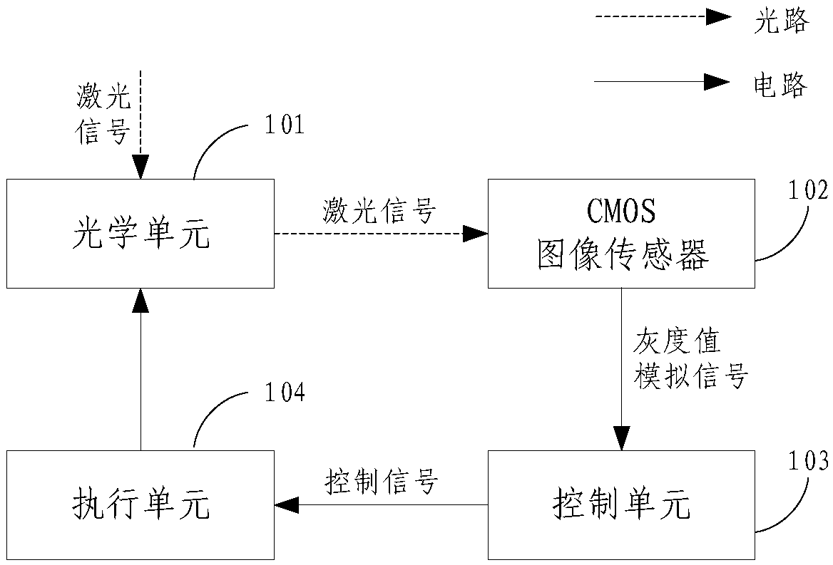
[0024] figure 1 It is a schematic structural diagram of a spot capturing system according to an embodiment of the present invention, such as figure 1 As shown, a spot capturing system includes an optical unit 101, a CMOS image sensor 102, a control unit 103, and an execution unit 104. The CMOS image sensor 102 is connected to the optic...


PUM


Abstract

The embodiment of the invention provides a light spot capturing system and method, and the system comprises an optical unit, a CMOS image sensor, a control unit and an execution unit, wherein the CMOSimage sensor is connected with the optical unit and the control unit, and the execution unit is connected with the control unit. The optical unit is used for receiving a laser signal, and the CMOS image sensor is used for sensing the laser signal and outputting a gray value analog signal. The control unit is used for acquiring a spot position error according to the gray value analog signal, and generating a control signal according to the spot position error, and the execution unit is used for adjusting the receiving angle of the optical unit according to the control signal. The system and method provided by the embodiments of the invention employ the CMOS image sensor, which is lower in cost and power consumption. A driving circuit is simpler, the transmission speed of signals and driving is higher, the parasitic delay is lower, and the reliability is higher, so the system and method meet the high requirements for a light spot capturing system in a wireless laser communication network in various application scenarios.

Description

technical field [0001] Embodiments of the present invention relate to the technical field of wireless laser communication, and in particular to a system and method for capturing light spots. Background technique [0002] As a new type of communication means, wireless laser communication has been more and more widely used because of its advantages of large channel capacity, high speed, strong confidentiality, low bit error rate and wide coverage. [0003] In the process of wireless laser communication, to ensure the stable communication of the laser communication system, the most critical step is to establish a laser communication link. The establishment process of the laser communication link is mainly to capture, track, and aim the beacon light in space, which is usually completed by the so-called ATP (Acquisition, Tacking, Pointing) system. In the ATP system, the first condition for establishing a laser communication link is to complete the capture of the laser signal, an...

Claims


Application Information

Patent Timeline
IPC IPC(8): H04N5/374H04N5/341H04B10/11
CPCH04B10/11H04N25/40H04N25/76
Inventor 罗南杭方明杰熊卿王强丁玮万华庆
Owner NO 719 RES INST CHINA SHIPBUILDING IND
Why Eureka
Try Eureka