Door locking mechanism and utilization method

A door locking and mechanism device technology, applied in applications, building locks, door/window accessories, etc., can solve the problems of low opening method, lack of novel functions, children hitting the door handle, etc., to improve safety and reliability. performance, achieve the effect of diversification and diversity utilization, and simple equipment structure

Inactive Publication Date: 2019-01-22
姚丽珍
View PDF0 Cites 5 Cited by
  • Summary
  • Abstract
  • Description
  • Claims
  • Application Information

AI Technical Summary

Problems solved by technology

[0002] The door is the first line of defense for family safety, and the safety of the door lock is particularly important. At present, the door lock mechanism is roughly divided into two types according to the opening method: automatic opening and manual opening, but the safety of a single opening method is low, and the existing There are few doors that integrate two opening methods. At the same time, when there are children in the family, it is easy for children to bump into the door handle when the door is closed. There are potential safety hazards, and the door handle has a single function and does not have novel functions. this kind of problem

Method used


Image

  • Door locking mechanism and utilization method
  • Door locking mechanism and utilization method
  • Door locking mechanism and utilization method

Examples


Embodiment Construction

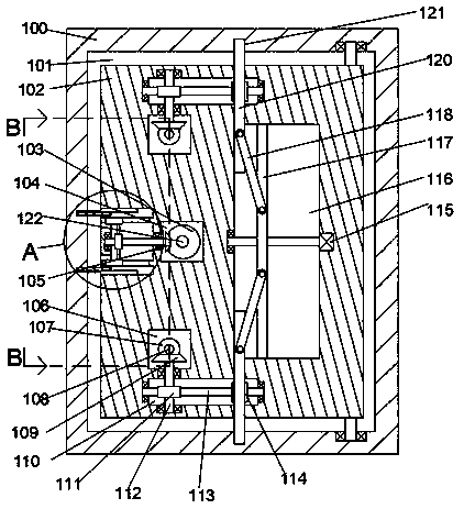
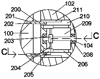
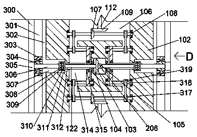
[0020] Combine below Figure 1-5 The present invention will be described in detail.

[0021] refer to Figure 1-5 According to a door locking mechanism and its use method according to an embodiment of the present invention, the door locking mechanism device includes a box body 100, a cavity 101 is fixed inside the box body 100, and the upper and lower end walls of the cavity 101 A top cavity 121 with an opening towards the center of the cavity 101 is provided, and a door 102 is installed on the upper and lower end walls of the cavity 101. The door 102 is fixed with an upper and lower symmetrical upper cavity 110, and the upper cavity 110 is far away from the The central end wall of the cavity 101 is rotatably provided with a rotating rod 112, the rotating rod 112 runs through the upper cavity 110, and the outer surface of the rotating rod 112 is fixed with a worm wheel 111 located in the upper cavity 110, so The left and right end walls of the upper chamber 110 are rotatably...


PUM


Abstract

The invention discloses a door locking mechanism and a utilization method thereof. The door locking mechanism comprises a chamber which is internally and fixedly provided with a cavity, upper and lower end walls of the cavity are provided with ejection cavities with openings towards the center of the cavity, and a door is rotationally arranged on upper and lower end walls of the cavity and fixedlyprovided with upper cavities in vertical symmetry. A rotating rod is rotationally arranged on the end wall, away from the center of the cavity, of each upper cavity and rotationally penetrates the corresponding upper cavity. A worm gear is fixedly arranged on the outer surface of each rotating rod and positioned in the corresponding upper cavity. A rotating shaft meshed with each worm gear is inrotational fit with left and right end walls of the corresponding upper cavity, and a gear is fixedly arranged on the outer surface of each rotating shaft. The door locking mechanism is simple in structure and convenient to use; multiple safety guarantees can be realized by adoption of automatic and manual operation structures; novel innovative design of traditional single-function equipment is realized through the novel mechanism, diversification and diversified utilization of the equipment can be realized, and safety and reliability are improved.

Description

technical field [0001] The invention relates to the field of doors, in particular to a door locking mechanism and a using method thereof. Background technique [0002] The door is the first line of defense for family safety, and the safety of the door lock is particularly important. At present, the door lock mechanism is roughly divided into two types according to the opening method: automatic opening and manual opening, but the safety of a single opening method is low, and the existing There are few doors that integrate two opening methods. At the same time, when there are children in the family, it is easy for children to bump into the door handle when the door is closed. There are potential safety hazards, and the door handle has a single function and does not have novel functions. This kind of problem. Contents of the invention [0003] The object of the present invention is to provide a door locking mechanism and its use method, which are used to overcome the above-m...

Claims


Application Information

Patent Timeline
Patent Type & Authority Applications(China)
IPC IPC(8): E05B47/00E05B5/00E05B3/00E05B17/00A61B5/107
CPCE05B47/0012A61B5/1072E05B3/00E05B5/00E05B17/00E05B2047/0018
Inventor 姚丽珍
Owner 姚丽珍
Why Eureka
Try Eureka