A variable stiffness elastic energy storage device and a method for testing rock instability using it

A technology of energy storage device and variable stiffness, which is applied in the direction of testing material strength by applying stable shear force, measuring device, and testing material strength by applying stable tension/pressure to achieve the effect of reducing friction

Active Publication Date: 2020-11-27
NORTHEASTERN UNIV LIAONING
View PDF9 Cites 0 Cited by
  • Summary
  • Abstract
  • Description
  • Claims
  • Application Information

AI Technical Summary

Problems solved by technology

At present, there is still a lack of testing instruments and corresponding testing methods for rock instability testing in the market.

Method used


Image

  • A variable stiffness elastic energy storage device and a method for testing rock instability using it
  • A variable stiffness elastic energy storage device and a method for testing rock instability using it
  • A variable stiffness elastic energy storage device and a method for testing rock instability using it

Examples


Embodiment 1

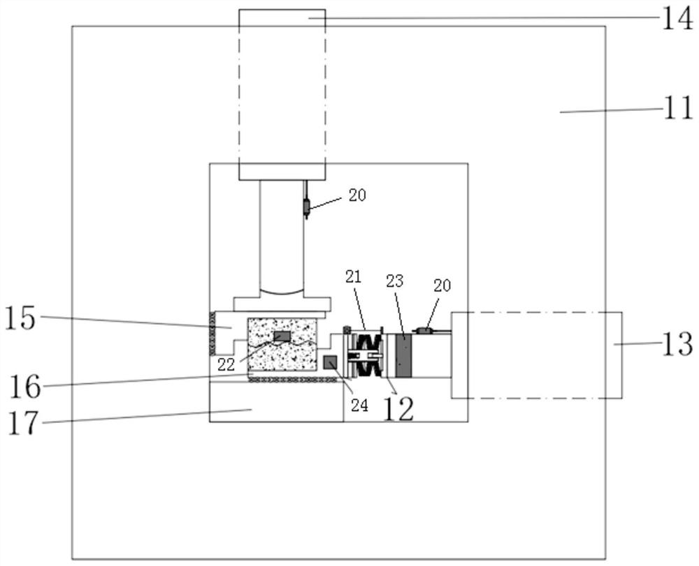
[0042] Such as figure 2As shown, a rock joint shear instability testing machine is an application of a variable stiffness elastic energy storage device on a conventional shear testing machine. It is composed of a conventional rock joint shear instrument and a variable stiffness elastic energy storage device, including a rigid frame structure 11, a variable stiffness elastic energy storage device 12, a tangential loading mechanism 13, a normal loading mechanism 14, an upper clamp 15 and a lower clamp 16 and block 17. The normal loading mechanism 14 is fixed on the upper part of the rigid frame structure 11 , the tangential loading mechanism 13 is fixed on one end of the rigid frame structure 11 , and the spacer 17 is fixed on the lower part of the rigid frame structure 11 . One end of the variable stiffness elastic energy storage device 12 is rigidly connected to the tangential loading mechanism 13 , and the other end is in contact with the lower clamp 16 .

[0043] The spec...

Embodiment 2

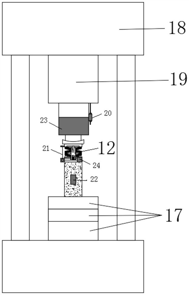
[0059] Such as image 3 As shown, a rock uniaxial compression instability testing machine is the application of the variable stiffness elastic energy storage device on the conventional uniaxial compression testing machine, and is composed of the conventional rock uniaxial compression testing machine and the variable stiffness elastic energy storage device , comprising a body frame 18, a variable stiffness elastic energy storage device 12, a loading cylinder 19, and a spacer 17. The loading oil cylinder 19 and the spacer 17 are fixed on the upper and lower ends of the body frame 18 respectively. One end of the variable stiffness elastic energy storage device 12 is in contact with the loading cylinder 19, and the other end is in contact with the upper surface of the rock sample, which is placed on the pad 17 of the testing machine.

[0060] The specific implementation plan is as follows:

[0061] Step 1: First, prepare a standard cylindrical rock sample;

[0062] Step 2: Plac...


PUM


Abstract

The invention belongs to the technical field of rock engineering, and particularly relates to a variable-stiffness elastic energy storage device and a method thereby for testing rock instability. Theinvention has the following technical scheme that the variable-stiffness elastic energy storage device comprises a pressure head, a guide rod, a base, a gasket and a disc spring, wherein the guide rodis vertically installed on the center of the base; the gasket and the disc spring are independently sheathed to the guide rod; the end of the guide rod is provided with a guide hole; the center of the pressure head is provided with a guide post; the guide post and the guide hole are matched; and the guide post is placed in the guide hole. By use of the variable-stiffness elastic energy storage device and the method thereby for testing rock instability, the variable-stiffness elastic energy storage device has the characteristics of small land occupation, large stiffness regulation range, convenience in processing and manufacture, low maintenance and repairing cost and long service life and can be combined with various rock mechanical test machines, and an instability testing method is adopted to test rock instability characteristics under different test conditions.

Description

technical field [0001] The invention belongs to the technical field of geotechnical engineering, and in particular relates to a variable stiffness elastic energy storage device and a method for testing rock instability using the same. Background technique [0002] The current rock mechanics testing machines are usually rigid or servo-controlled testing machines. People often focus on obtaining a constant deformation rate and achieving a stable loading process, while ignoring the rock instability itself during the loading process. Significance. In fact, whether it is the rupture of crustal rocks and dislocation of faults in nature, or rock bursts and rock bursts caused by rock engineering, most natural and engineering disasters show the phenomenon of rock instability and destruction. Among them, the instability and slippage of geological faults, rockbursts in mine pillars and tunnels often lead to serious natural disasters and engineering accidents, resulting in heavy casual...

Claims


Application Information

Patent Timeline
Patent Type & Authority Patents(China)
IPC IPC(8): G01N3/24G01N3/12G01N3/08
CPCG01N3/08G01N3/12G01N3/24G01N2203/0019G01N2203/0025G01N2203/0075G01N2203/0252G01N2203/0256
Inventor 朱万成董航宇刘溪鸽徐曾和于永军代凤程关文
Owner NORTHEASTERN UNIV LIAONING
Why Eureka
Try Eureka