Novel storage device
A new type of material storage technology, applied in packaging, large containers, transportation and packaging, etc., can solve the problems of material failure of the storage device, single structure of the storage device, and inability to keep the temperature of the storage device constant, so as to avoid quality problems. Fluctuation, use effect guaranteed effect
- Summary
- Abstract
- Description
- Claims
- Application Information
AI Technical Summary
Problems solved by technology
Method used
Image
Examples
Embodiment 1
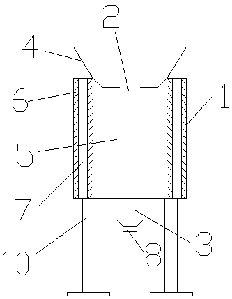
[0015] A novel material storage device is provided with a tank body 1, a feed port 2 is provided on the tank body 1, a discharge port 3 is provided under the tank body 1, and the feed port 2 is provided. There is a material guide plate 4 on it, the material guide plate 4 is arranged along the side of the feed port 2, and a material storage cavity 5 is arranged under the said feed port 2, and the said tank body 1 and the material storage cavity are A thermal insulation board 6 is arranged between the thermal insulation boards 6 , a support board 7 is arranged between the thermal insulation boards 6 , the two sides of the support board 7 are attached to the thermal insulation board 6 , and a split board 8 is arranged under the discharge port 2 .
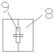
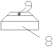
[0016] The said split plate 8 is composed of two sets of mutually symmetrical iron plates, and a locking pin 9 is arranged between the split plates 8 .
[0017] The locking pin 9 and the split plate 8 are provided with keyholes to coop...
Embodiment 2
[0020] A novel material storage device is provided with a tank body 1, a feed port 2 is provided on the tank body 1, a discharge port 3 is provided under the tank body 1, and the feed port 2 is provided. There is a material guide plate 4 on it, the material guide plate 4 is arranged along the side of the feed port 2, and a material storage cavity 5 is arranged under the said feed port 2, and the said tank body 1 and the material storage cavity are A thermal insulation board 6 is arranged between the thermal insulation boards 6 , a support board 7 is arranged between the thermal insulation boards 6 , the two sides of the support board 7 are attached to the thermal insulation board 6 , and a split board 8 is arranged under the discharge port 2 .
[0021] The said split plate 8 is composed of two sets of mutually symmetrical iron plates, and a locking pin 9 is arranged between the split plates 8 .
[0022] The locking pin 9 and the split plate 8 are provided with keyholes to coop...
Embodiment 3
[0026] A novel material storage device is provided with a tank body 1, a feed port 2 is provided on the tank body 1, a discharge port 3 is provided under the tank body 1, and the feed port 2 is provided. There is a material guide plate 4 on it, the material guide plate 4 is arranged along the side of the feed port 2, and a material storage cavity 5 is arranged under the said feed port 2, and the said tank body 1 and the material storage cavity are A thermal insulation board 6 is arranged between the thermal insulation boards 6 , a support board 7 is arranged between the thermal insulation boards 6 , the two sides of the support board 7 are attached to the thermal insulation board 6 , and a split board 8 is arranged under the discharge port 2 .
[0027] The said split plate 8 is composed of two sets of mutually symmetrical iron plates, and a locking pin 9 is arranged between the split plates 8 .
[0028] The locking pin 9 and the split plate 8 are provided with keyholes to coop...
PUM
 Abstract
Description
Claims
Application Information
 - R&D
- Intellectual Property
- Life Sciences
- Materials
- Tech Scout
- Unparalleled Data Quality
- Higher Quality Content
- 60% Fewer Hallucinations
Browse by: Latest US Patents, China's latest patents, Technical Efficacy Thesaurus, Application Domain, Technology Topic, Popular Technical Reports.
© 2025 PatSnap. All rights reserved.Legal|Privacy policy|Modern Slavery Act Transparency Statement|Sitemap|About US| Contact US: help@patsnap.com


