Method and system for detecting position of drilled hole in roadway
A drilling position and roadway technology, which is applied in the direction of measuring device, electromagnetic measuring device, point coordinate measurement, etc., can solve the problems of difficulty in obtaining accurate drilling position, inconvenient underground construction, and detection.
- Summary
- Abstract
- Description
- Claims
- Application Information
AI Technical Summary
Problems solved by technology
Method used
Image

Examples
no. 1 example
[0045] The charging method is an electrical exploration method that directly charges the good conductors that have been exposed on the ground, in the tunnel or in the borehole, and understands the size of the ore body by observing the spatial distribution of the charging field. It is mainly used in metal mines or groundwater flow detection.
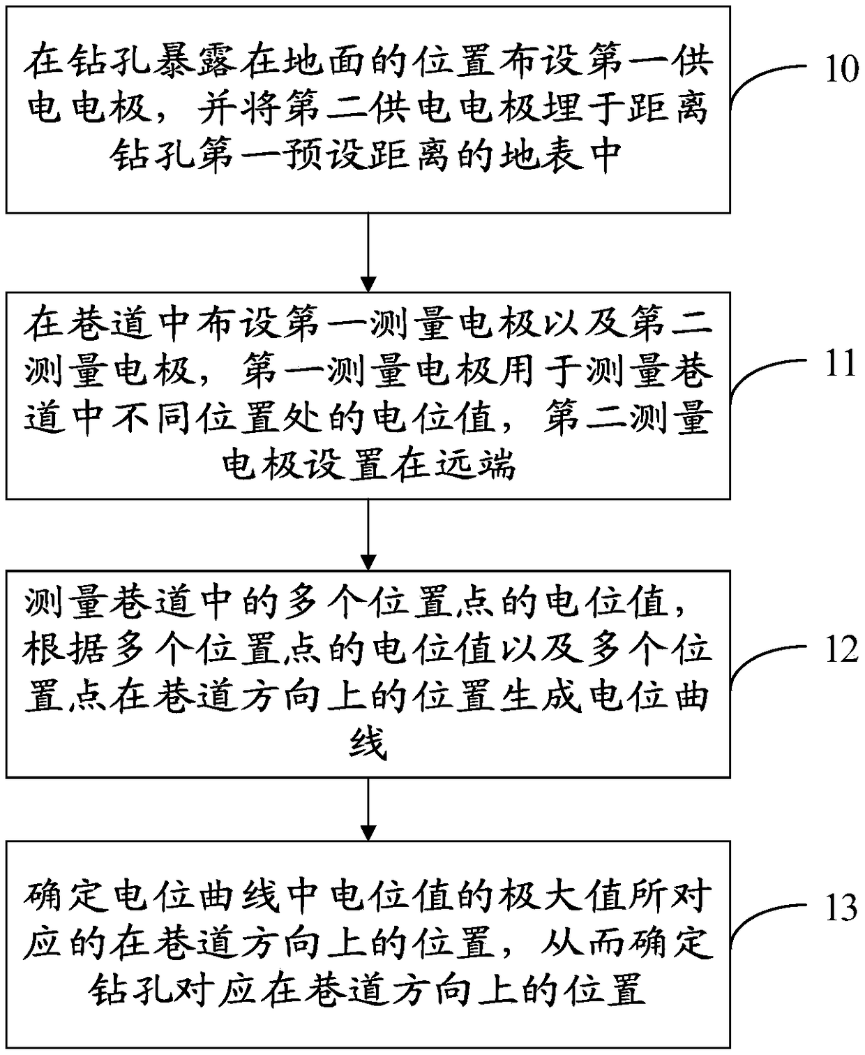
[0046] This embodiment provides a method for detecting the position of a borehole in a roadway. The charging method is applied to the underground of a coal mine, and the position of a metal observation hole with a smaller aperture in the direction of the roadway can be detected in the underground roadway. By determining the position of the drill hole, the It brings convenience in the actual production and construction process of coal mines. For example, the shortest distance of the tunnel can be used to find the borehole during construction, and avoid digging waste roadways. Please refer to figure 1 , the method for detecting the borehole...
Embodiment approach
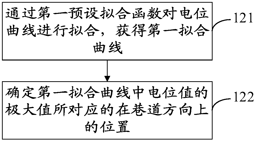
[0062] Optionally, see image 3 In the above step 13, an implementation manner of determining the position corresponding to the maximum value of the potential value in the potential curve in the direction of the roadway includes:
[0063] Step 121: Fitting the potential curve with a first preset fitting function to obtain a first fitting curve.
[0064] Since the measured multiple potential values are discrete data points, the potential curve generated based on these multiple discrete data points is not accurate enough. A series of discrete data points in the coordinates can be used as a smooth curve through the preset fitting function Connection, the fitting curve generated by different preset fitting functions is different, in practical application, it can be set freely according to the actual situation.
[0065] Step 122: Determine the position in the roadway direction corresponding to the maximum value of the potential value in the first fitting curve.
[0066] Since t...
no. 2 example
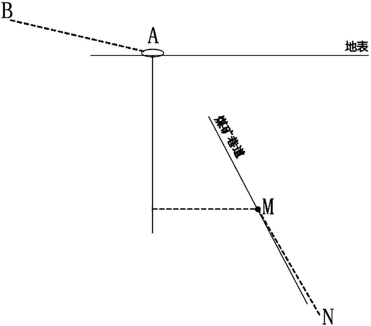
[0076] This embodiment provides a system for detecting the position of a borehole in a roadway, see Figure 7 , including: a power supply device 100 and a receiving device 101, the power supply device 100 is connected to the first power supply electrode A through a first cable, and connected to the second power supply electrode B through a second cable, and the first power supply electrode A is laid in a drill hole exposed At the outcrop position on the ground surface, for example, it is connected to the metal casing of the borehole. The power supply device 100 supplies power to the borehole through the first power supply electrode A, and the second power supply electrode B connected to the power supply device 100 is buried in a certain distance from the borehole. On the ground surface, as an electrode at infinity; the receiving device 101 is connected to the first measuring electrode M through the third cable, and connected to the second measuring electrode N through the fourt...
PUM
 Abstract
Description
Claims
Application Information
 - R&D
- Intellectual Property
- Life Sciences
- Materials
- Tech Scout
- Unparalleled Data Quality
- Higher Quality Content
- 60% Fewer Hallucinations
Browse by: Latest US Patents, China's latest patents, Technical Efficacy Thesaurus, Application Domain, Technology Topic, Popular Technical Reports.
© 2025 PatSnap. All rights reserved.Legal|Privacy policy|Modern Slavery Act Transparency Statement|Sitemap|About US| Contact US: help@patsnap.com