Vibration damping device

A technology for anti-vibration devices and mounting components, applied in the direction of shock absorbers, shock absorber-spring combinations, springs/shock absorbers, etc., can solve problems such as abnormal sounds, achieve suppression of abnormal sounds, and simple structure Effect

Active Publication Date: 2019-02-05
BRIDGESTONE CORP
View PDF5 Cites 0 Cited by
  • Summary
  • Abstract
  • Description
  • Claims
  • Application Information

AI Technical Summary

Problems solved by technology

Then, under the action of the suddenly generated negative pressure, a cavitation phenomenon occurs in which a large number of bubbles are generated in the liquid, and further, abnormal noise may be generated due to cavitation rupture of the generated bubbles.

Method used


Image

  • Vibration damping device
  • Vibration damping device

Examples


Embodiment Construction

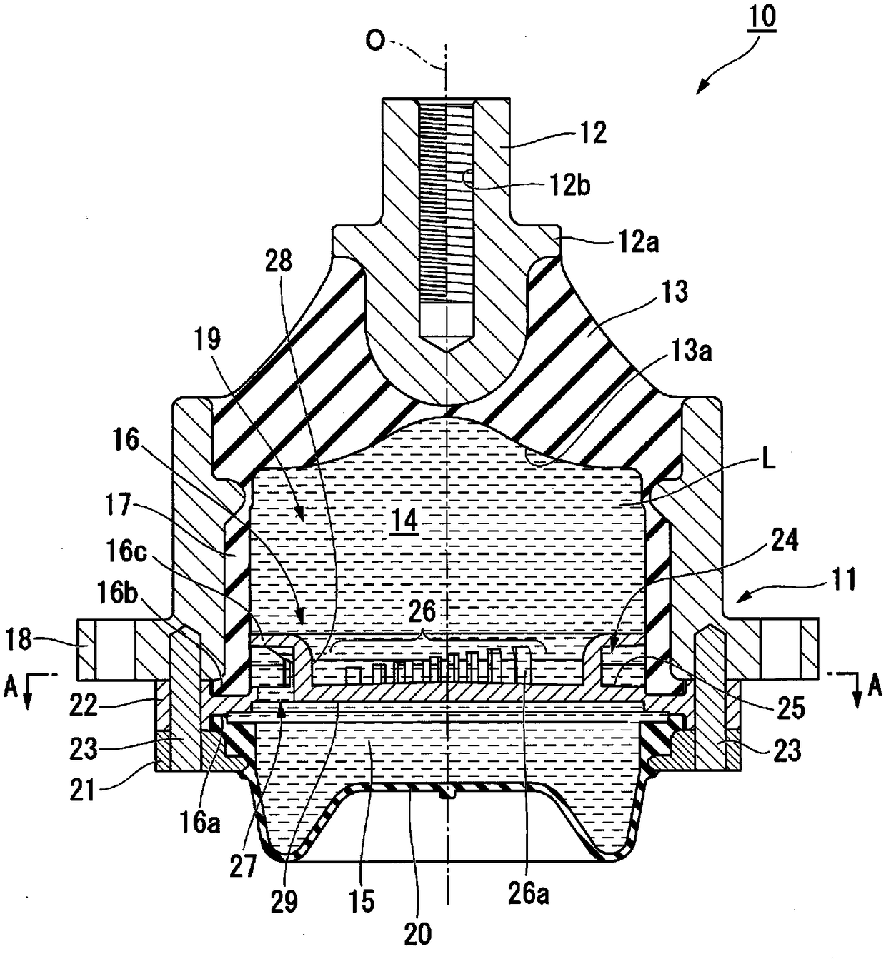
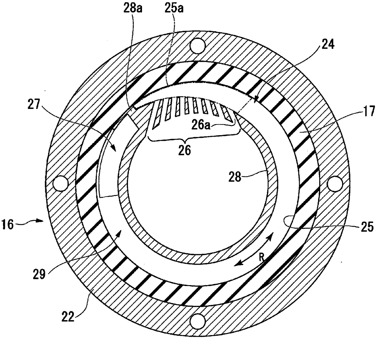
[0018] Below, based on figure 1 with figure 2 , the embodiment of the anti-vibration device of the present invention will be described.

[0019] Such as figure 1 As shown, the anti-vibration device 10 is a liquid-enclosed anti-vibration device, which includes: a first mounting member 11, which is cylindrical and connected to any one of the vibration generating part and the vibration receiving part; the second mounting member 12 , which is connected to the other of the vibration generating part and the vibration receiving part; the elastic body 13, which is used to elastically connect the above-mentioned first mounting member 11 and the second mounting member 12 to each other; and a partition member 16, which It is used to divide the inside of the first mounting member 11 into a main liquid chamber 14 and a secondary liquid chamber 15 which will be described later.

[0020] Hereinafter, the central axis of the first mounting member 11 is referred to as the axis O, and the...


PUM


Abstract

This vibration damping device (10) is provided with a first attachment member (11), a second attachment member (12), an elastic body (13) and a partition member (16). In the partition member, a restricted passageway (24) is formed which allows communication between a first liquid chamber (14) and a second liquid chamber (15). The restricted passageway is provided with a first communication unit (26) which opens to the first liquid chamber, a second communication unit (27) which opens to the second liquid chamber, and a main body flow path (25) which allows communication between the first communication unit and the second communication unit. At least one of the first communication unit and the second communication unit is provided with multiple fine holes (26a) arranged along the flow pathdirection of the main body flow path. The further away the fine holes are positioned from the other of the first communication unit and the second communication unit in the flowpath direction, the greater the flow path length.

Description

technical field [0001] The present invention relates to an anti-vibration device for absorbing and reducing vibration of a vibration-generating part such as an engine, applied to, for example, automobiles, industrial machines, and the like. [0002] This application claims priority based on Japanese Patent Application No. 2016-124986 for which it applied in Japan on June 23, 2016, and uses the content here. Background technique [0003] As this kind of anti-vibration device, there is known a kind of structure in the past, and it comprises: and the first mounting member of cylindrical shape that links in one of vibration generating part and vibration receiving part and with the other in vibration generating part and vibration receiving part. a second mounting member connected by one; an elastic body for connecting the above two mounting members; and a liquid chamber for dividing the liquid chamber in the first mounting member sealed with liquid into a main liquid chamber and ...

Claims


Application Information

Patent Timeline
IPC IPC(8): F16F13/10
CPCF16F13/10F16F13/107B60K5/1208F16F2230/36
Inventor 植木哲佐竹勇树永泽正和长岛康寿之菅原英树大野信吾
Owner BRIDGESTONE CORP
Why Eureka
Try Eureka