Drilling device convenient to use for furniture production

A drilling device and furniture technology, applied in portable drilling rigs, drilling/drilling equipment, manufacturing tools, etc., can solve the problems of reducing production time and labor costs of manufacturers, small operating space, unreasonable design of drilling devices, etc. , to achieve the effect of convenient replacement of punching positions, convenient movement and placement, and small and light equipment

Inactive Publication Date: 2019-02-12
江西春阳家具集团有限公司
View PDF5 Cites 0 Cited by
  • Summary
  • Abstract
  • Description
  • Claims
  • Application Information

AI Technical Summary

Problems solved by technology

[0002] Drilling motor is a drilling tool that uses electricity as power. It is a necessary electric tool in furniture production, and it is also the electric tool with the largest demand. It is only relying on the motor to drive the transmission gear to increase the force of the drill bit to make the drill bit scrape through the furniture material. While drilling, it can ensure that the entire material is not damaged. The convenience and high efficiency of the drilling motor greatly reduce Due to the production time and labor cost of the manufacturers, there are many types of drilling devices for furniture production on the market, but most of the manufacturers have limited workshop space. Most of the drilling devices for furniture production are large in equipment and small in operating space, which is difficult for technicians to operate. bring a lot of inconvenience
[0003] The design of existing drilling devices for furniture production is unreasonable. Small equipment has many restrictions on material width, and large equipment has few restrictions on material width. However, it is difficult to move and place, and cannot meet the needs of many manufacturers in the market.

Method used


Image

  • Drilling device convenient to use for furniture production
  • Drilling device convenient to use for furniture production
  • Drilling device convenient to use for furniture production

Examples


Embodiment Construction

[0027] The following will clearly and completely describe the technical solutions in the embodiments of the present invention with reference to the accompanying drawings in the embodiments of the present invention. Obviously, the described embodiments are only some, not all, embodiments of the present invention. Based on the embodiments of the present invention, all other embodiments obtained by persons of ordinary skill in the art without making creative efforts belong to the protection scope of the present invention.

[0028] In the description of the present invention, it should be noted that the terms "center", "upper", "lower", "left", "right", "vertical", "horizontal", "inner", "outer" etc. The indicated orientation or positional relationship is based on the orientation or positional relationship shown in the drawings, and is only for the convenience of describing the present invention and simplifying the description, rather than indicating or implying that the referred d...


PUM


Abstract

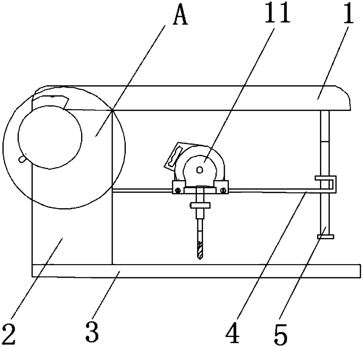
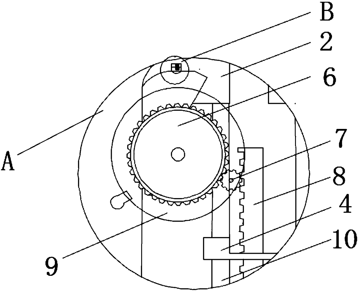
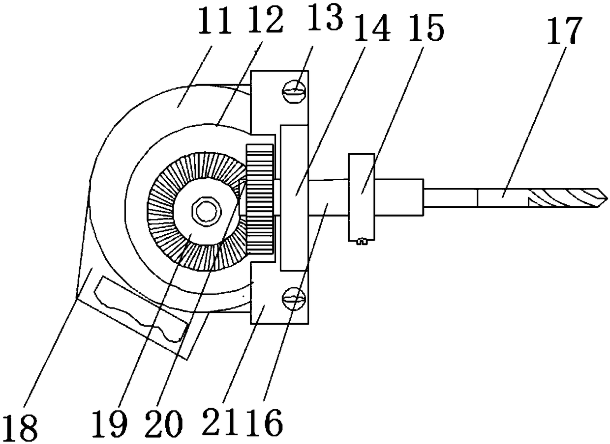
The invention discloses a drilling device convenient to use for furniture production. The drilling device comprises a U-shaped top cover, the bottom face of the U-shaped top cover is connected with anadjusting work cabinet, the end, away from the adjusting work cabinet, of the U-shaped top cover is connected with a nail-shaped column, a wheel ring spring bolt is embedded to the bottom face of theU-shaped top cover, the inner side of the wheel ring spring bolt is connected with a return spring, the bottom face of the adjusting work cabinet is connected with a flat plate base, a rotary gear isarranged in an inner cavity of the adjusting work cabinet, one side o the rotary gear is fixedly connected with a control wheel ring, a linkage gear is arranged in an inner cavity of the adjusting work cabinet, a metal cylinder is arranged in the inner cavity of the adjusting work cabinet, the surface of the metal cylinder is sleeved and connected with a metal sliding way, and a lifting rack is welded to one end of the metal sliding way. In the drilling device, the overall structure is in a C shape, equipment is small, portable and convenient to move and place, gear pressing is adopted for drilling pressing, a motor is provided with an adaptor, and drill bits with different diameters can be easily replaced.

Description

technical field [0001] The invention relates to the field of drilling tools, in particular to an easy-to-use drilling device for furniture production. Background technique [0002] Drilling motor is a drilling tool that uses electricity as power. It is a necessary electric tool in furniture production, and it is also the electric tool with the largest demand. It is only relying on the motor to drive the transmission gear to increase the force of the drill bit to make the drill bit scrape through the furniture material. While drilling, it can ensure that the entire material is not damaged. The convenience and high efficiency of the drilling motor greatly reduce Due to the production time and labor cost of the manufacturers, there are many types of drilling devices for furniture production on the market, but most of the manufacturers have limited workshop space. Most of the drilling devices for furniture production are large in equipment and small in operating space, which is ...

Claims


Application Information

Patent Timeline
Patent Type & Authority Applications(China)
IPC IPC(8): B23B45/02B25H1/00
Inventor 曾乐引
Owner 江西春阳家具集团有限公司
Why Eureka
Try Eureka