
Mechanical arm capable of clamping in rotary mode

A technology of a robotic arm and a rotating shaft, applied in the field of robotic arms, can solve problems such as uneconomical space utilization, and achieve the effect of high locking structure strength, simple structure, and increasing applicable scenarios.

Pending Publication Date: 2019-02-15
HANGZHOU JIMU TECH CO LTD
View PDF0 Cites 0 Cited by
  • Summary
  • Abstract
  • Description
  • Claims
  • Application Information

AI Technical Summary

Problems solved by technology

The comb-tooth robot needs to build a special parking platform, lift the car, and then lift it up and consign it, resulting in uneconomical space utilization

Method used


Image

  • Mechanical arm capable of clamping in rotary mode
  • Mechanical arm capable of clamping in rotary mode
  • Mechanical arm capable of clamping in rotary mode

Examples


Embodiment Construction

[0032] The present invention will be described in further detail below in conjunction with the accompanying drawings and specific embodiments.

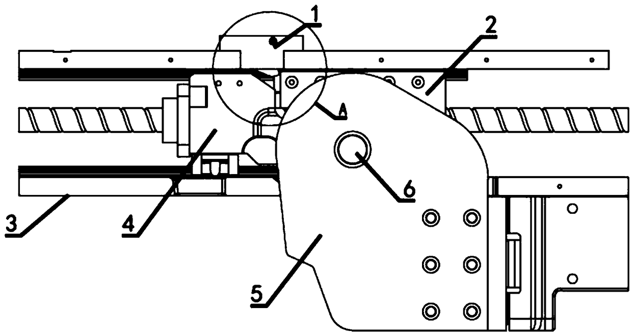
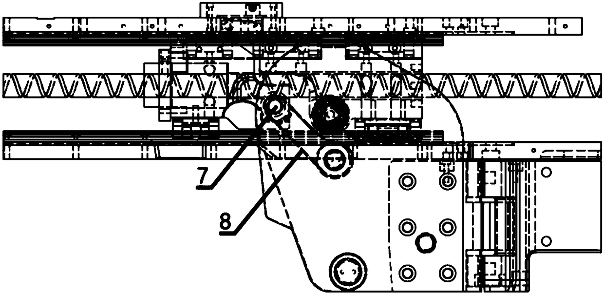
[0033] The invention provides a new type of rotatable clamping mechanical arm, including a lock pin device 1, a locking limit block 2, a frame 3, a driving device 4, a mechanical arm body 5, a mechanical arm rotation shaft 6, and a drive connection shaft 7 and drive tie rod 8, see figure 1 and image 3 .

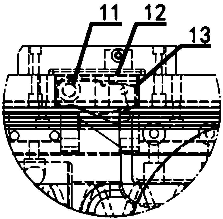
[0034] Described lock pin device 1 comprises lock pin rotating shaft 11, lock pin spring seat 12 and lock pin 13 etc., see figure 2 .

[0035] Described driving device 4 comprises leading screw 41, nut seat 42, driving block 43 etc., see Figure 4 .

[0036] The manipulator body 5 includes a clamping arm body 51, an upper connecting plate 52 of the mechanical arm, an upper connecting plate thrust column 53, a lower connecting plate thrust column 54, a lower connecting plate 55 of the mechanical arm, etc., see Figure 4 .

[...


PUM


Abstract

The invention discloses a mechanical arm capable of clamping in a rotary mode. The mechanical arm comprises a locking pin device, a locking limiting block, a rack, a drive device, a mechanical arm body, a mechanical arm rotary shaft, a drive connecting shaft and a drive pulling rod, wherein the locking pin device is mounted on the rack; the drive device comprises a lead screw and a drive block; the drive block and the rack define a slide block guide rail structure, and the drive block can slide along the rack; the drive block is connected with the drive pulling rod through the drive connectingshaft; the drive pulling rod is connected with the mechanical arm body; the locking limiting block and the rack define a slide block guide rail structure, and the locking limiting block can slide along the rack; the mechanical arm body is connected with the locking limiting block through a mechanical arm rotary shaft; a thrust column is arranged on the mechanical arm body; and a groove capable ofallowing the thrust column to pass through is formed in the rack. The mechanical arm can move after being completely unfolded, can realize limiting closing action in a moving process, is high in structural strength of the locking structure, is simple in structure, is reliable in work, and increases a mechanical arm applicable scene.

Description

technical field [0001] The invention belongs to the field of mechanical arms, in particular to a rotatable and gripping mechanical arm used by a wheeled robot. Background technique [0002] With the rapid development of society, cars are becoming more and more popular, but the parking problem that comes with it has become a difficult problem in major and medium cities. In order to solve the problems of difficult and inefficient parking in existing parking lots and new parking lots, the application of intelligent parking robots is becoming more and more common. At present, there are several types of smart robots for accessing cars, such as those with car plates, combs, and robotic arms. In the prior art, the vehicle-carrying plate robot has to always bear the vehicle-carrying plate, which is the lowest in terms of space utilization and transportation efficiency. The comb-tooth robot needs to build a special parking platform, lift the car, and then carry out lifting consignm...

Claims


Application Information

Patent Timeline
IPC IPC(8): B25J5/00B25J18/00
CPCB25J5/007B25J18/00
Inventor 王晨曹力郭雨
Owner HANGZHOU JIMU TECH CO LTD
Learn More