
A composite mechanical lock structure

A technology of mechanical lock and locking structure, applied in the field of robotics, can solve the problem of high structural height of the mechanical arm, achieve the effect of small size, increase the applicable scene, and reduce the height of the local structure

Active Publication Date: 2019-10-15
HANGZHOU JIMU TECH CO LTD
View PDF10 Cites 0 Cited by
  • Summary
  • Abstract
  • Description
  • Claims
  • Application Information

AI Technical Summary

Problems solved by technology

Due to the high structural height of the mechanical arm, the existing mechanical arm parking robot is not suitable for some vehicles with low chassis or chassis armor

Method used


Image

  • A composite mechanical lock structure
  • A composite mechanical lock structure
  • A composite mechanical lock structure

Examples


Embodiment Construction

[0017] The present invention will be described in further detail below in conjunction with the accompanying drawings and specific embodiments.

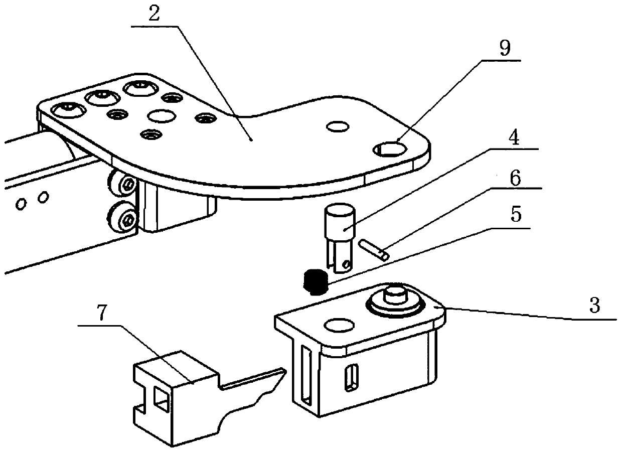
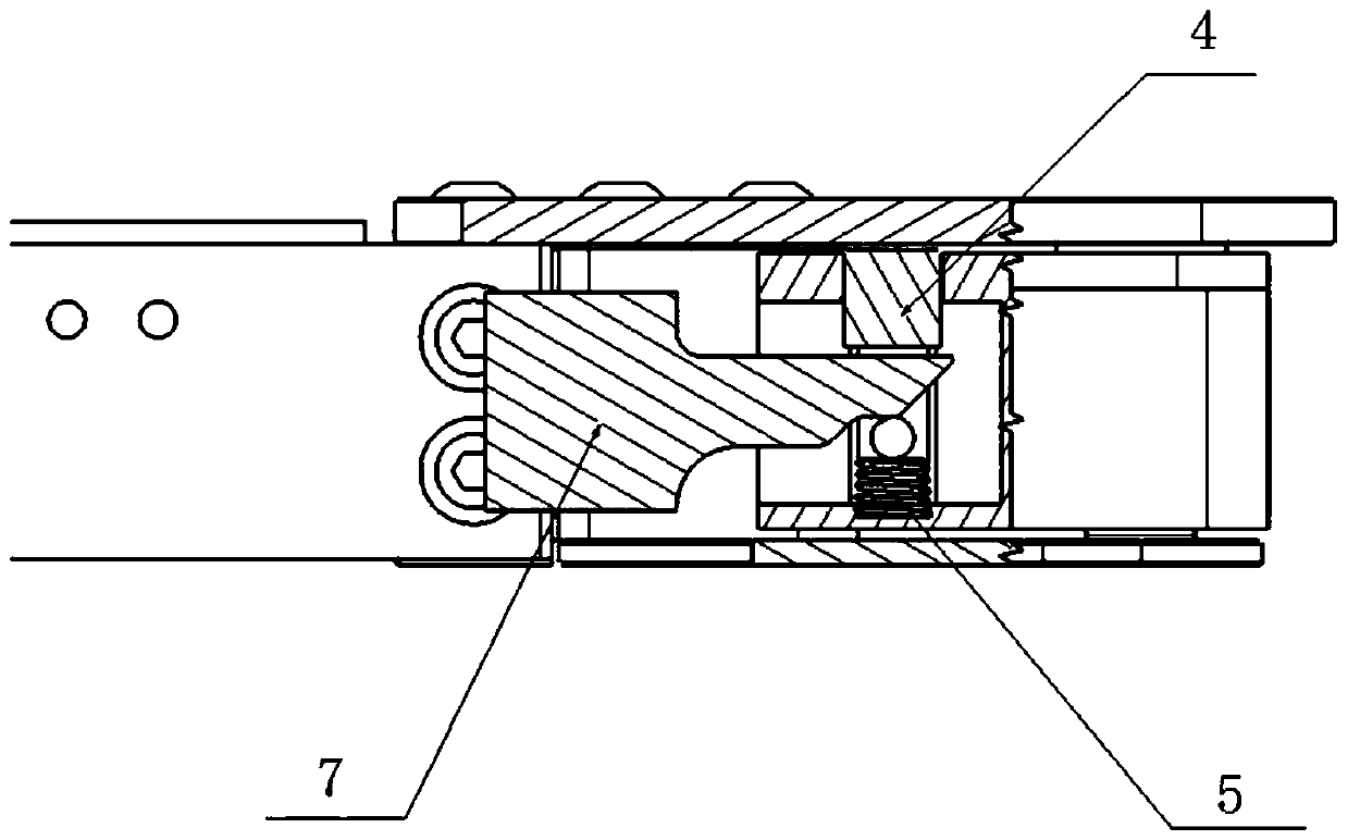
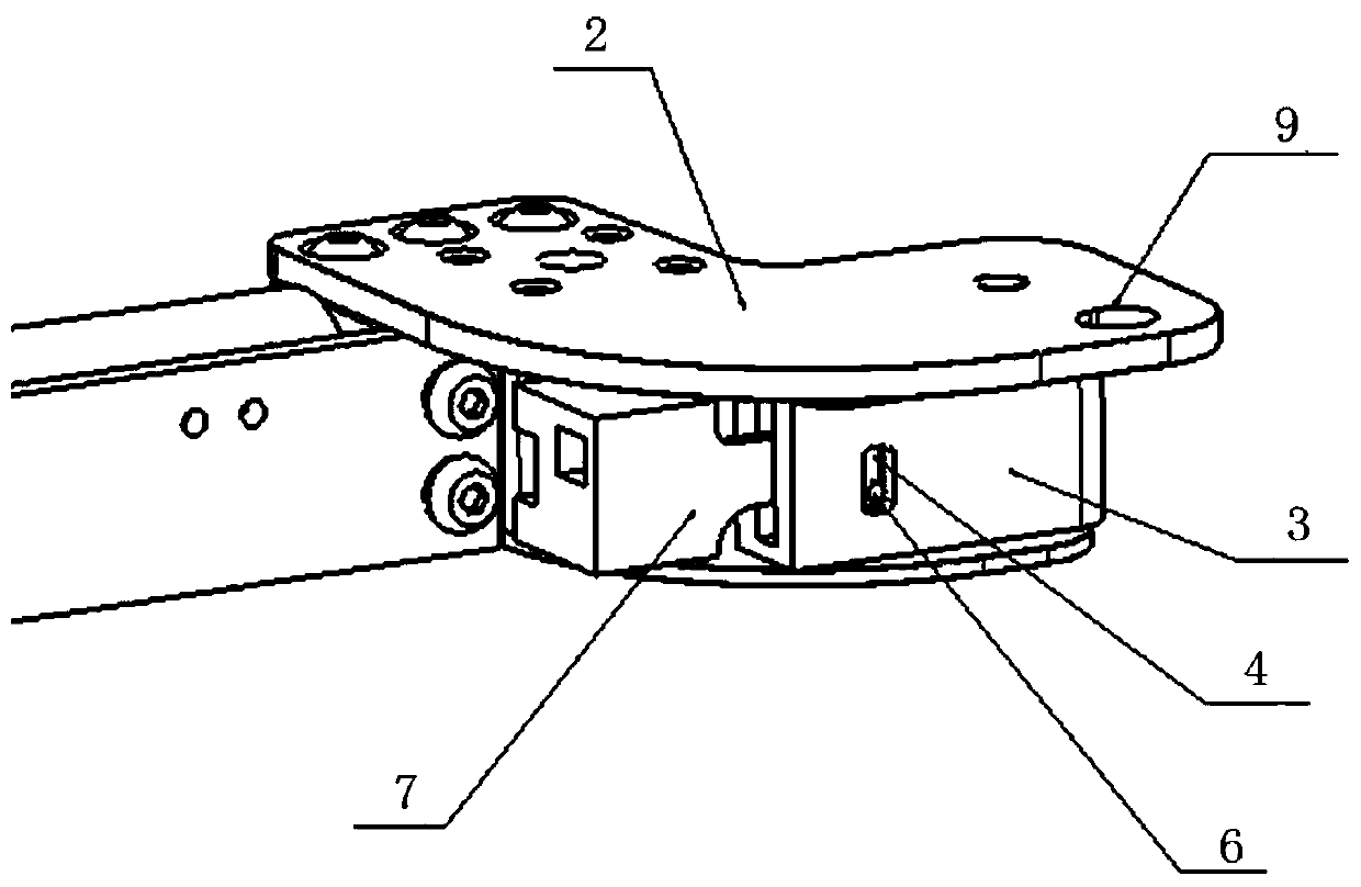
[0018] Such as figure 1 As shown, a composite mechanical lock structure provided by the present invention includes: a locking structure base 3, a locking pin 4, an unlocking pin 7, a locking pin limiting shaft 6 and a mechanical arm mounting plate 2; the locking The first side of the structural base 3 is provided with an unlocking pin accommodating groove, the second side adjacent to the first side is provided with a locking pin limiting shaft limiting hole, and the upper surface is provided with a locking pin accommodating groove; The lock pin 4 includes an upper lock end and a lower guide end, and the lower guide end has a guide through hole and a lock pin limit shaft installation hole; as shown in Figure 2, the unlock pin 7 is inserted into the guide of the lock pin 4 In the through hole; the locking pin limiting shaft 6 passes th...


PUM


Abstract

The invention discloses a composite mechanical lock structure which comprises a locking structure base, a locking pin, an unlocking pin, a locking pin limiting shaft and a mechanical arm installationplate. When a mechanical arm rotates, the mechanical arm installation plate rotates along with the mechanical arm. When a mechanical arm installation plate limiting hole and the locking pin are concentric, the locking pin moves in the direction limited by the locking pin limiting shaft under thrust of a spring till the locking pin enters the mechanical arm installation plate limiting hole, and themechanical arm is locked at the moment. When the locking structure makes contact with the unlocking pin, the unlocking pin compresses the locking pin guiding shaft so as to compress the spring, recycle the locking pin and release locking, and the mechanical arm can rotate again after the locking pin is recycled. The locking pin is used for locking the mechanical arm to limit rotation, the strength of the locking structure is high, the size is small, the structure is simple, work is reliable, the local structural height of the mechanical arm can be reduced, the movement envelope of the mechanical arm is reduced, the application scene of the mechanical arm is enlarged, and therefore the mechanical arm can be applied to scenes with more compact space.

Description

technical field [0001] The invention belongs to the technical field of robots, and in particular relates to a composite mechanical lock structure. Background technique [0002] With the development of the robot industry in my country in recent years, more and more fields have begun to use robots to increase labor productivity, which can reduce labor costs and labor intensity and improve production efficiency. As artificial intelligence robots are no longer limited to the fields of industry and production, robots are beginning to appear in more and more civilian fields. The popularity of cars in modern society is getting higher and higher, and the space of parking lots is becoming more and more cramped. Therefore, with the popularization of artificial intelligence, parking robots have emerged. This robot can automatically park for users, arrange parking spaces reasonably, and use the parking space reasonably. Existing manipulator type parking robot is not applicable to the v...

Claims


Application Information

Patent Timeline
Patent Type & Authority Patents(China)
IPC IPC(8): F16B21/12B25J19/00
Inventor 王晨
Owner HANGZHOU JIMU TECH CO LTD
Learn More