Tire structure for wheelchair

A technology for tires and wheelchairs, which is applied to tire parts, tire treads/tread patterns, transportation and packaging, etc. It can solve the problems of labor-intensive promotion, single performance, and weak grip, so as to save labor and reduce potential safety hazards , the effect of good grip performance

Pending Publication Date: 2019-02-15
CHENG SHIN RUBBER (XIAMEN) IND LTD
View PDF0 Cites 18 Cited by
  • Summary
  • Abstract
  • Description
  • Claims
  • Application Information

AI Technical Summary

Problems solved by technology

However, under the condition of high wind pressure, the contact area between the tread and the road surface of the slick tire is reduced, and the edge effect of the tread is insufficient. At this time, the grip is weaker, which is likely to cause safety hazards.
In addition, compared with bicycle tires, wheelchair tires are used on both sides side by side, mainly performing various actions such as forward, backward, and turning, while the current slick tires are lighter and more agile when performing forward actions, and their performance is relatively single, which is not fully applicable The backward, turning and other actions performed by the wheelchair, especially when turning, are not smooth and agile enough, which may even cause another form of pushing effort

Method used


Image

  • Tire structure for wheelchair
  • Tire structure for wheelchair
  • Tire structure for wheelchair

Examples


Embodiment Construction

[0036] The present invention will be described in further detail below in conjunction with the accompanying drawings and specific embodiments.

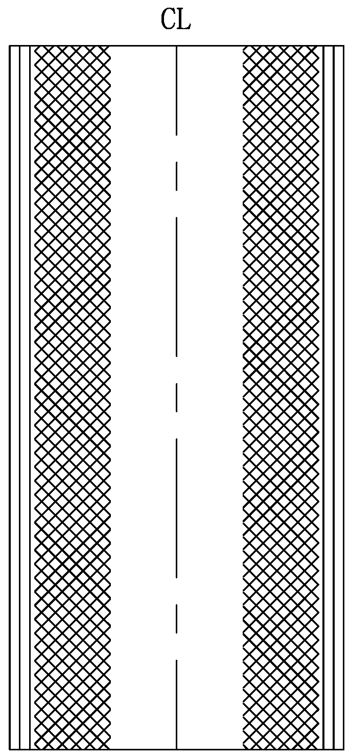
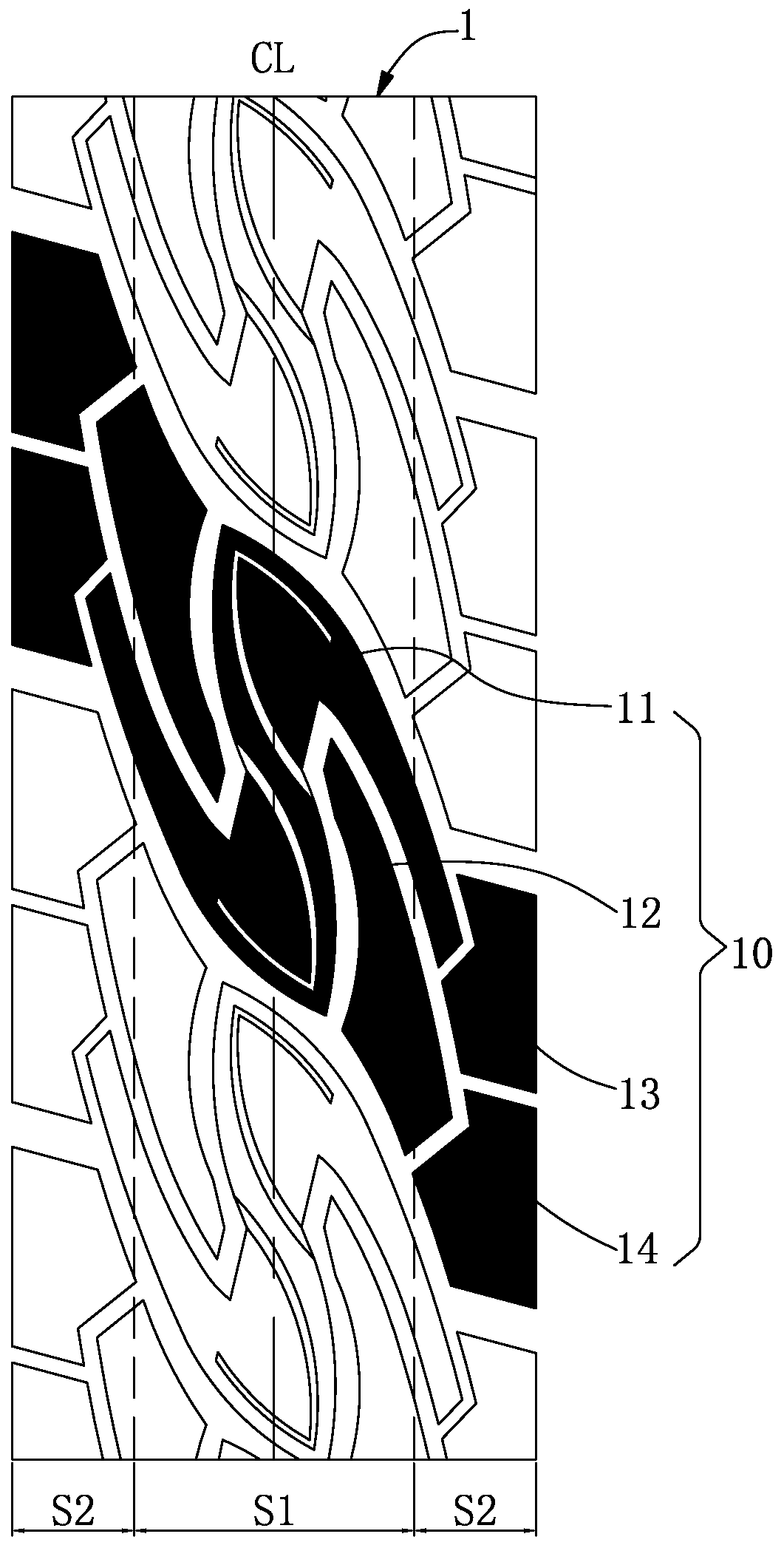
[0037] Such as Figure 2 to Figure 6 As shown, the present invention discloses a wheelchair tire structure. exist Figure 2 to Figure 5 The vertical direction is the tire circumferential direction, the transverse direction is the tire axial direction, and the single dotted line represents the tread centerline CL. exist Image 6 In the middle, the vertical direction is set as the tire radial direction, the transverse direction is the tire axial direction, and the single dotted line indicates the equatorial plane.

[0038] Such as figure 2 Shown is a tread pattern of the tire tread of the present invention, in view of the actual use of wheelchair tires, such as Image 6 As shown, the tread 1 is divided into the contact area S1 and two transition areas S2, where the contact area S1 is figure 2 The area defined between the two das...


PUM


Abstract

The invention discloses a tire structure for a wheelchair. A plurality of pattern groups are uniformly distributed at intervals on a tread of a tire in the circumferential direction, each pattern group contains an inverted S-shaped pattern block on the center line of the tread, and each inverted S-shaped pattern block comprises a central axle part and two flank parts, wherein the two correspondingflank parts are at 180 degrees from each other along the center of the tread. The central axle parts are located on the center line of the tread and are in a concave-convex shape with a wide upper end, a narrow middle end and a wide lower end in the circumferential direction of the tire. The two flank parts of the inverted S-shaped pattern blocks are arranged on one sides of the upper and lower ends of the central axle parts in an opposite mode. According to the tire structure for the wheelchair, through the structural design of the inverted S-pattern blocks on the center line of the tread, so that the inverted S-pattern blocks located at the center of the tread has double directionality, the tire can be switched smoothly between forward, backward, rotation and any other movement, the wheelchair is enabled to be labor-saving in pushing, agile and durable, a good catching performance is played, and safety hazards are reduced.

Description

technical field [0001] The invention relates to a tire, in particular to a wheelchair tire structure used for a wheelchair wheel. Background technique [0002] Wheelchairs are not only a rehabilitation tool for the physically disabled and people with reduced mobility, but also an important tool for them to travel, exercise and participate in social activities. Wheelchairs include large wheels and small wheels, of which the large wheels carry the main weight. Currently, most large wheels are equipped with pneumatic tires except for a few use environments that require solid tires. Pneumatic tires require light weight and durability. In order to be easy to push, a higher air pressure is usually filled in the tire to reduce the friction between the tread and the road surface and reduce rolling resistance, but it is easy to cause safety hazards due to insufficient grip. And the damping effect when driving on uneven roads is relatively poor, causing personnel discomfort. [0003...

Claims


Application Information

Patent Timeline
Patent Type & Authority Applications(China)
IPC IPC(8): B60C11/03
CPCB60C11/032
Inventor 黄鑫焱林文艳
Owner CHENG SHIN RUBBER (XIAMEN) IND LTD
Why Eureka
Try Eureka