Developer conveyance device, developing device, and image forming device

Active Publication Date: 2011-07-14
KONICA MINOLTA BUSINESS TECH INC
View PDF5 Cites 5 Cited by
  • Summary
  • Abstract
  • Description
  • Claims
  • Application Information

AI Technical Summary

Benefits of technology

[0042]According to the present invention, it is possible to convert effectively the direction of the developer from the axial direction to the direction being perpendicular to the axial direction since a plurality of paddle parts are formed in the delivery region of the developer conveyance member.

Problems solved by technology

However, according to the constitution described in Patent Document 1, as described in the paragraph of 004

Method used


Image

  • Developer conveyance device, developing device, and image forming device
  • Developer conveyance device, developing device, and image forming device
  • Developer conveyance device, developing device, and image forming device

Examples


Embodiment Construction

[0053]Hereinafter, the embodiment(s) according to the present invention will be described with reference to the drawings. Further, in the following explanation, as necessary, the terms showing specific directions and positions (for example, “above”, “below”, “side”, “end”, and other terms including these terms) are used; however, these terms are used in order to make the understanding of the invention with reference to the drawings easy and due to meanings of these terms, the technical scope of the present invention is not limited.

(Constitution)

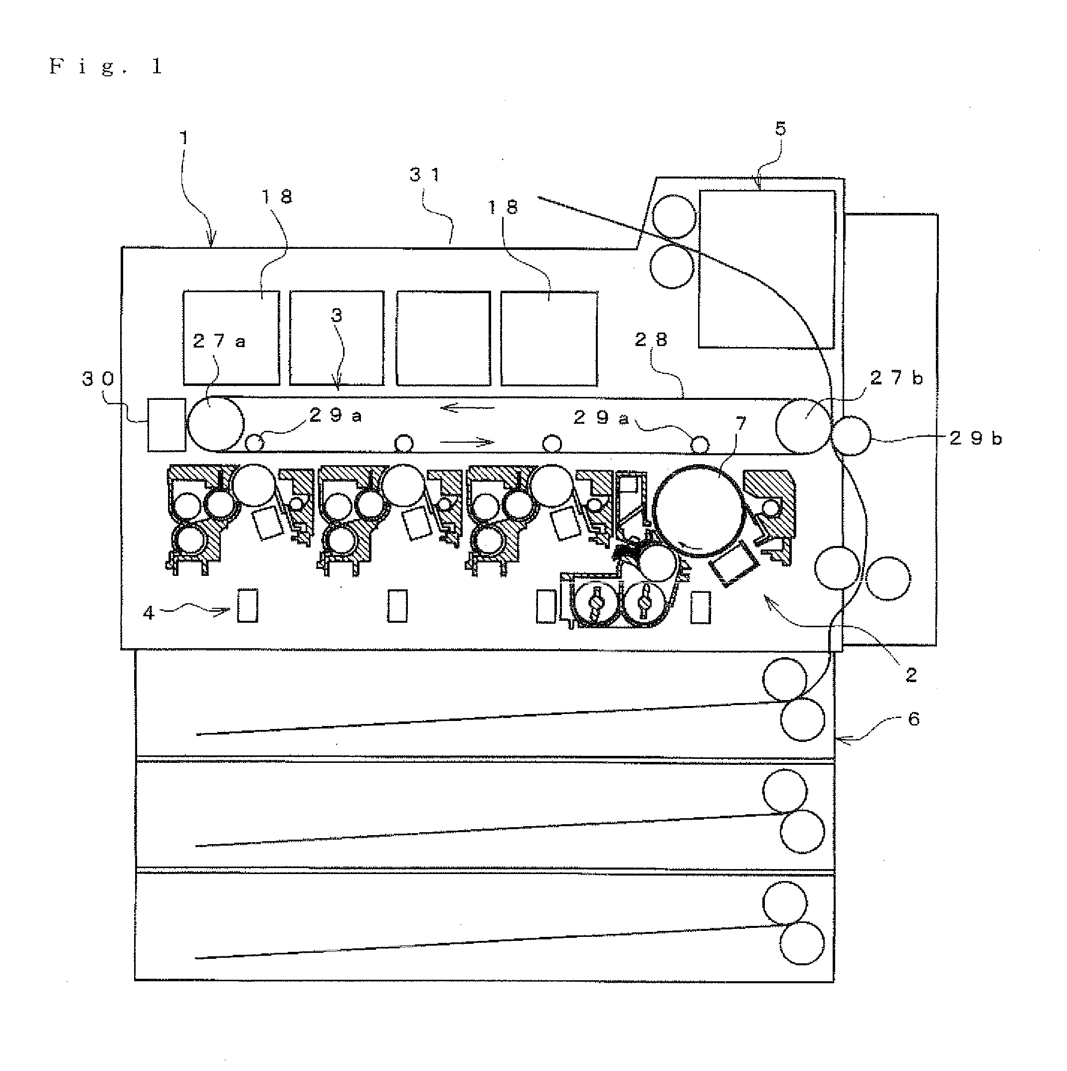
[0054]FIG. 1 shows a tandem color image forming device applying an electro-photographic technology according to the present embodiment. However, the present invention is not only applied to this kind of image forming device 1, and for example, the present invention can be applied to a so-called four-cycle system color image forming device and the image forming device 1 of a black-and-white output. In addition, the present invention can be als...


PUM


Abstract

There is provided a developer conveyance member that conveys a contained developer from one end side of a delivery region to other end of the delivery region while agitating the contained developer in a developer container, in which the developer is contained. Around a rotation shaft of the developer conveyance member, a spiral wing toward from one end side to other end side is formed. A plurality of paddle parts for conveying the developer in a direction that is perpendicular to a shaft core are formed around the rotation shaft in a delivery region. The paddle parts are arranged with their positions deviated in a circumferential direction.

Description

[0001]This application is based on Japanese Patent Application No. 2008-239031 filed in Japan on Sep. 18, 2008, the entire content of which is hereby incorporated by reference.BACKGROUND OF THE INVENTION[0002]1. Field of the Invention[0003]The present invention relates to a developer conveyance device for conveying a developer while converting a direction of this developer, a developing device being provided with this developer conveying device, and an image forming device that is adopted by a copy machine, a printer, a facsimile apparatus, or by a multifunction machine provided with these functions.[0004]2. Description of the Related Art[0005]Conventionally, as a developing device, one has been publicly known, in which, forming an agitating member on a rotation shaft of a first conveyance member, and agitating a developer by means of this agitating member, then, the developer is conveyed from a first circulation region to a second circulation region (for example, refer to Japanese ...

Claims


Application Information

Patent Timeline
IPC IPC(8): G03G15/08
CPCG03G15/0822G03G2215/0841G03G2215/0838
Inventor YOSHIMOTO, SHINICHIMAEDA, OSAMU
Owner KONICA MINOLTA BUSINESS TECH INC
Why Eureka
Try Eureka