Eureka AIR delivers breakthrough ideas for toughest innovation challenges, trusted by R&D personnel around the world.

Plastic stool injection mold base for preventing reinforcing ribs from dragging damage during demolding

A technology for injection molding and plastic stools, which can be applied to home appliances, other home appliances, and household components. It can solve the problems of unstable stool support, stool thickness reduction, and insufficient draft angle of injection molds, etc., to achieve flexible adjustment of inclination , optimize stability, and improve the effect of insufficient product protection

Active Publication Date: 2019-02-19
重庆天骄塑料包装有限责任公司
View PDF6 Cites 0 Cited by
  • Summary
  • Abstract
  • Description
  • Claims
  • Application Information

AI Technical Summary

Problems solved by technology

[0004] Aiming at the deficiencies in the prior art, the purpose of the present invention is to provide a plastic stool injection molding mold base based on preventing ribs from being dragged out of the mold, so as to solve the problem of partial collapse of the mold due to insufficient draft angle of the injection mold. Deformation, so that the side wall of the molded part rubs against the mold when the mold is ejected, because the steel surface of the side wall has burrs and is very rough, and the mold is tilted and scratched when the mold is ejected, causing fire patterns, skin patterns and other wear and tear patterns on the molded parts, resulting in unqualified injection molded products, stools Thickness is reduced and the stool is unstable

Method used


Image

  • Plastic stool injection mold base for preventing reinforcing ribs from dragging damage during demolding
  • Plastic stool injection mold base for preventing reinforcing ribs from dragging damage during demolding
  • Plastic stool injection mold base for preventing reinforcing ribs from dragging damage during demolding

Examples


Embodiment Construction

[0026] In order to make the technical means, creative features, goals and effects achieved by the present invention easy to understand, the present invention will be further described below in conjunction with specific embodiments.

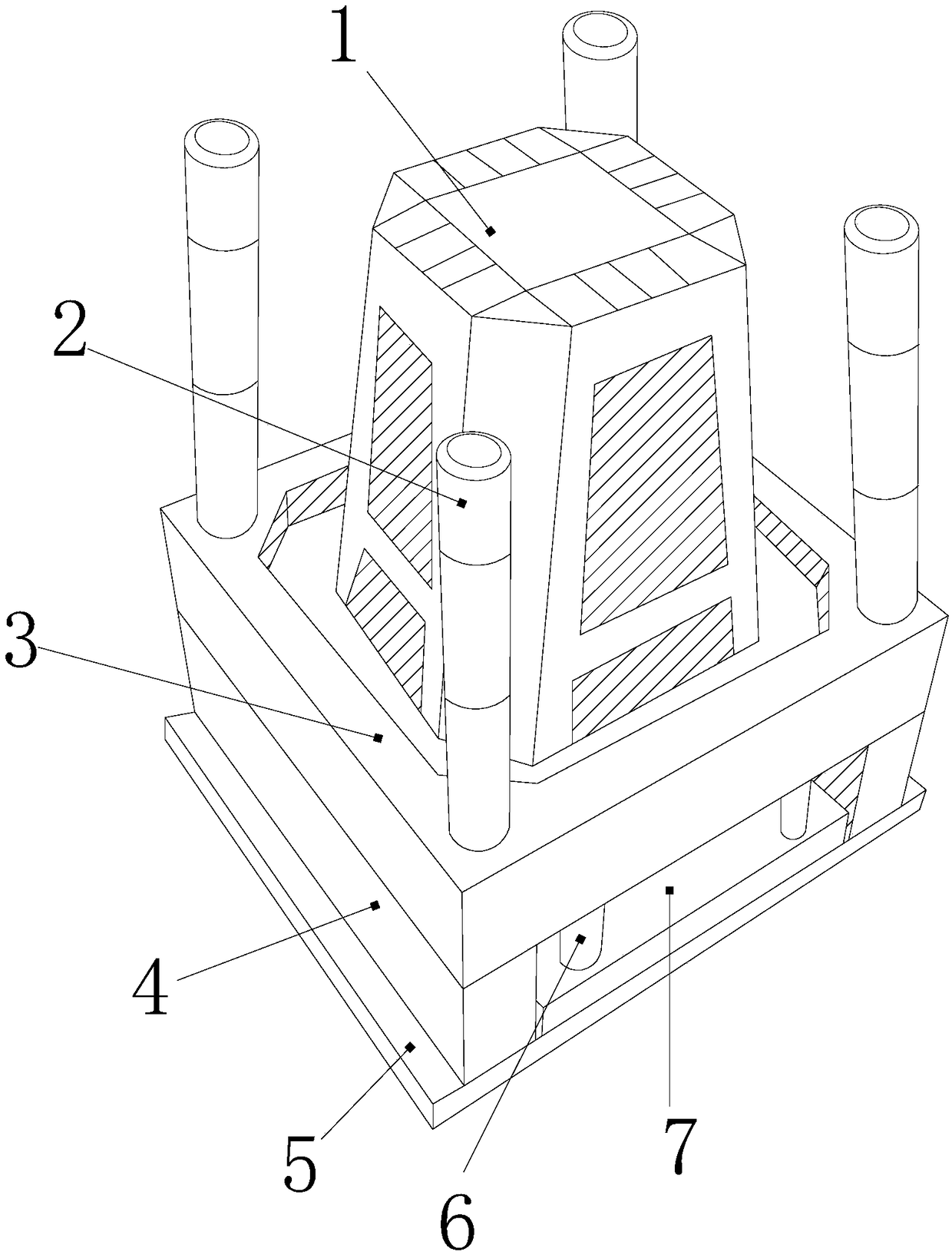
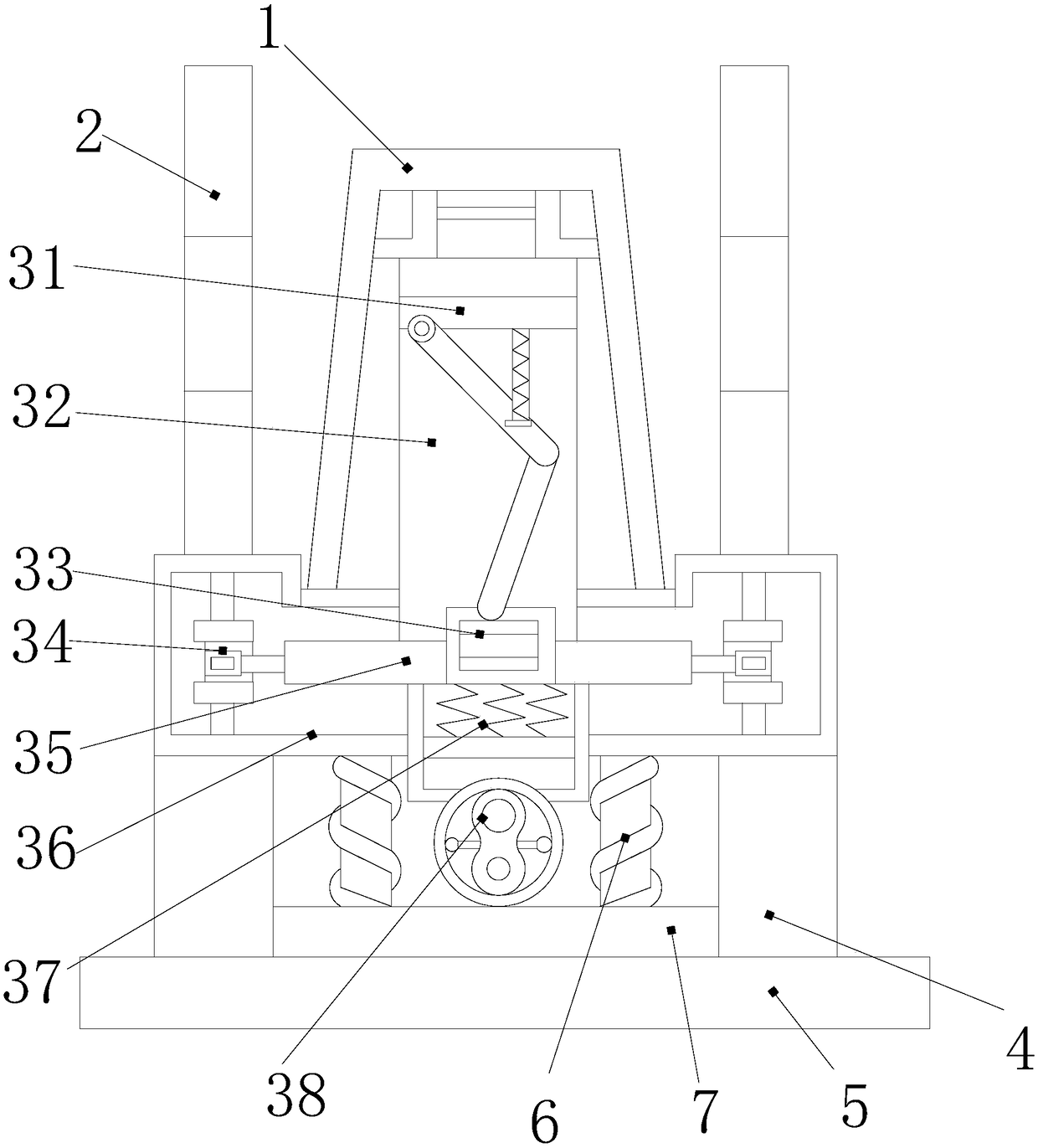
[0027] see Figure 1-Figure 5, the present invention provides a plastic stool injection molding mold base based on anti-reinforcing ribs, the structure includes: mold shell plate 1, pin column 2, cylinder ejector 3, base pad 4, Base 5, torsion spring column 6, liner 7, the base block 4 is provided with two and respectively close to the left and right lower corners of the cylinder ejector 3, the torsion spring column 6 is provided with two and respectively Inserted in the left and right upper corners of the liner 7, the bottom surface of the liner 7 is close to the top surface of the base 5 and is on the same level, the base block 4 and the base 5 are welded into one, the latch There are four columns 2 and they are respectively inserted and embedd...


PUM


Abstract

The invention discloses a plastic stool injection mold for preventing reinforcing ribs from dragging damage during demolding. The plastic stool injection mold base structurally comprises a plastic mold shell board, a bolt column, an ejector sleeve ejector, two base cushion blocks, a pedestal, two torsion spring columns and a liner, wherein the two base cushion blocks are attached to the lower leftcorner and the lower right corner of the ejector sleeve ejector separately, the two torsion spring columns are inserted and embedded at the upper left corner and the upper right corner of the liner separately. The plastic mold shell board and the ejector sleeve ejector cooperate, a worker performs pushing and pressing with a thick push rod and a thin push rod of a bevel adjuster, the thick push rod is used for making a rotary lug plate to jack the front end of a sliding plate of a spring seat to tilt so as to push a finished product out, the effect of flexibly adjusting the inclination is achieved, and then the thin push rod pushes a steel reed pipe to balance the rear end of the sliding plate so as to prevent scratch loss, so that a linkage connection rod push frame has upward acting force on the plastic mold shell board in an ejector sleeve body, a product is discharged out of a mold with the inclination of the front side being well controlled, then the rear side is integrally jacked to lift the mold, the product protection effect of the mold is improved, and the stability of product quality is optimized.

Description

technical field [0001] The invention relates to an injection molding mold base for a plastic stool based on the anti-damage of reinforcing ribs when ejected from the mold, and belongs to the field of injection molds. Background technique [0002] The plastic stool injection molding mold has a long stool, so the mold base pushes the bumps higher, which is convenient to take out the mold, and in the pressurization process of the injection molding, it also matches the template polishing and covers the injection molding, so the molded plastic mold has sharp edges and corners It is very delicate and beautiful, but the gap between the formed stool legs and the ribs is long, so that the draft angle is not enough and it is easy to be scratched. The shortcomings of the current technology that need to be optimized are: [0003] Because the draft angle of the injection mold is not enough, it will cause local collapse and deformation of the mold, so that the side wall of the molded part...

Claims


Application Information

Patent Timeline
IPC IPC(8): B29C43/36B29C43/50B29L31/44
CPCB29C43/36B29C43/50B29C2043/503B29L2031/44
Inventor 许俊佳
Owner 重庆天骄塑料包装有限责任公司
Why Eureka
Eureka Blog
Learn More