Traction ball joint with adjustable torsional stiffness, and torsional stiffness regulating method

A technology of torsional stiffness and adjustment method, which is applied in the field of rail transit, can solve problems such as differences in stiffness adjustment methods, and achieve the effects of large axial stiffness and torsional stiffness, large deflection angle, and small radial stiffness and deflection stiffness

Inactive Publication Date: 2019-02-19
ZHUZHOU TIMES NEW MATERIALS TECH
View PDF13 Cites 0 Cited by
  • Summary
  • Abstract
  • Description
  • Claims
  • Application Information

AI Technical Summary

Problems solved by technology

[0008] Although the above-mentioned patent also draws on the technical content of the traction ball joint and rigidity, it does not have the second inner sleeve embedded in the first inner sleeve, the first outer sleeve is embedded in the second outer sleeve, and the second inner sleeve and the second inner sleeve are connected by a rubber body. The first outer cover is vulcanized together; the second inner cover includes a structure such as a triangular inner cover main body, which is also very different from the present invention in the method of stiffness adjustment

Method used


Image

  • Traction ball joint with adjustable torsional stiffness, and torsional stiffness regulating method
  • Traction ball joint with adjustable torsional stiffness, and torsional stiffness regulating method
  • Traction ball joint with adjustable torsional stiffness, and torsional stiffness regulating method

Examples


Embodiment 1

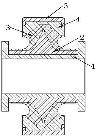
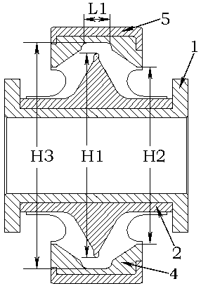
[0027] The traction ball joint is a rotating body, and the section of the traction ball joint is as follows: figure 1 As shown, the traction ball joint includes a first inner sleeve 1 , a second inner sleeve 2 , a rubber body 3 , a first outer sleeve 4 and a second outer sleeve 5 . The cross-section of the first inner sleeve 1 is T-shaped, and the cross-section formed by the assembly of two T-shaped first inner sleeves 1 is figure 1 The "工" font in. The two ends of the first inner sleeve 1 are bent to form a groove, and the second inner sleeve 2 is embedded in the groove of the first inner sleeve 1, so that the first inner sleeve 1 can prevent the second inner sleeve 2 from Axial direction movement.

[0028] The second inner sleeve 2 includes a bottom plate 21 and an inner sleeve main body 22, and the bottom plate 21 and the inner sleeve main body 22 are seamlessly connected as a whole. The bottom plate 21 is in the shape of a tube, the cross section of the inner sleeve bod...

Embodiment 2

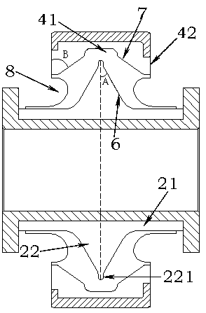
[0036] The difference between this embodiment and the first embodiment is that no raised boss 221 is provided on the top of the inner sleeve main body 22 , and only the top of the inner sleeve main body 22 is made into a circular arc surface. Therefore, the value of the thinnest vertical fork thickness in this embodiment refers to half of the difference between the maximum length of the top arc surface of the inner sleeve main body 22 and the length of the minimum inner diameter outside the first outer sleeve 4 .


PUM


Abstract

The invention provides a traction ball joint with adjustable torsional stiffness, and a torsional stiffness regulating method. A second inner sleeve is embedded in a first inner sleeve, and a first outer sleeve is embedded in a second outer sleeve; the second inner sleeve and the first outer sleeve are vulcanized together through a rubber body; and the second inner sleeve comprises an inner sleevemain body with a triangular section, and the axial stiffness of the traction ball joint can be regulated through the difference value between the maximum outer diameter of the inner sleeve main bodyand the minimum inner diameter of the first outer sleeve. According to the traction ball joint, the axial stiffness and the torsional stiffness of the traction ball joint are high, and the radial stiffness and the deflection stiffness are low. The both sides of the rubber body are provided with rubber grooves, so that the traction ball joint has a large deflection angle. The requirements of a structure without an axle bogie for the technology and performance of the traction ball joint can be met.

Description

technical field [0001] The invention relates to the field of rail transportation, in particular to a traction ball joint with adjustable stiffness. Background technique [0002] Spain's TALGO is mainly engaged in the research and development of high-speed EMU vehicles, covering a speed of 160 kilometers to 350 kilometers per hour, and its main technology is axleless bogies, which are completely different from traditional bogies such as BT, AT and domestic models. The biggest feature of this axleless bogie is that the two wheels of the same bogie can pass through the track curve at a differential speed, reducing wheel rim wear, and the vehicle is more stable when passing the curve, but at the same time, it is not suitable for various load conditions of metal rubber parts. worse. [0003] The structure of the axleless bogie has high requirements on the technology and performance of the traction ball joint. In terms of stiffness, the axial stiffness and torsional stiffness of ...

Claims


Application Information

Patent Timeline
Patent Type & Authority Applications(China)
IPC IPC(8): F16F1/387F16F1/376
CPCF16F1/376F16F1/3856F16F1/387F16F2228/06F16F2232/02
Inventor 雷军玉林胜罗斌庄征宇贺小龙曾慧
Owner ZHUZHOU TIMES NEW MATERIALS TECH
Why Eureka
Try Eureka