Flow control method and system for diversion shaft

A flow control and diverter well technology, which is applied in waterway systems, sewage removal, drainage structures, etc., can solve the problems of electric shock hazard, easy leakage, and high cost, and achieves a high-level space, strong anti-blocking ability, and simple construction. Effect

Pending Publication Date: 2019-02-22
WUHAN SHENGYU DRAINING SYST
View PDF18 Cites 4 Cited by
  • Summary
  • Abstract
  • Description
  • Claims
  • Application Information

AI Technical Summary

Problems solved by technology

However, in reality, electric control has the following problems: 1. Generally, flammable and explosive biogas will be produced in closed pipelines and sewage environments. General electric control devices are prone to explosion and unsafe. Therefore, when using electric control devices It is required that the electronic control part in contact with the biogas must have an explosion-proof function, so the price of the electronic control system is relatively expensive and the cost is high; 2. In the severe environment of stormy weather, power failure will occur, and the power will be diverted after power failure The equipment in the diversion well, abandonment well or interception well cannot work normally, resulting in urban waterlogging and other situations; 3. In rainy weather, the flooding of diversion wells, abandonment wells and interception wells ranges from several hours to several days In this way, the use of an electronic control device that is completely suitable for underwater use will be too redundant and cost too high, and the commonly used IP68-level electronic control device can be submerged within a few hours, and there are also situations where the capacity is insufficient; 4. The devices of the electric control system use unsafe voltage, and the high voltage is unsafe and prone to accidents; 5. After the electrical equipment is flooded, it is easy to leak electricity and there is a risk of electric shock; 6. When the electric control equipment (gates, weirs) are running It needs an upward or downward journey, which exposes the urban ground, which affects the urban landscape and traffic, and the excavation area is large during construction; 7. The electric control system uses 380V three-phase electricity, and the municipal power grid cannot supply power, so there is a problem of power supply difficulty question
[0004] In particular, for the occasions requiring concealed installation, and the power supply and costs of the electronic control system are not easy to solve
There are also certain problems in hydraulic control: the hydraulic station uses high-pressure oil pipes, and the cost of the hydraulic station and high-pressure oil pipes is relatively high; the rupture of high-pressure oil pipes will pollute the environment; after the electrical equipment is flooded, it is easy to leak electricity and there is a risk of electric shock; Gates, weir gates) require upward or downward strokes during operation, exposing the urban ground, affecting the urban landscape and traffic, and the excavation area is large during construction
[0005] In addition, the existing interception wells can only realize the control of on and off, and cannot carry out convenient and accurate flow control

Method used


Image

  • Flow control method and system for diversion shaft
  • Flow control method and system for diversion shaft
  • Flow control method and system for diversion shaft

Examples


Embodiment 1

[0056] Embodiment 1 of the present invention provides a flow control method for a diverter well:

[0057] Set the predetermined flow value,

[0058] The measured flow value of the second water outlet pipe is a real-time measured value, and the relationship between the real-time measured value and the flow value is compared,

[0059] When the real-time measured value is greater than the set flow value, the controller sends a control signal to drive the control valve to operate the pneumatic shut-off device to inflate, and the second outlet pipe tends to close until the measured value is equal to the set flow value, and the pneumatic shut-off device stops inflated;

[0060] When the real-time measured value is less than the set flow value, the controller sends a control signal to drive the control valve to operate the pneumatic shut-off device to deflate, and the second outlet pipe tends to open until the measured value is equal to the set flow value, and the pneumatic shut-off...

Embodiment 2

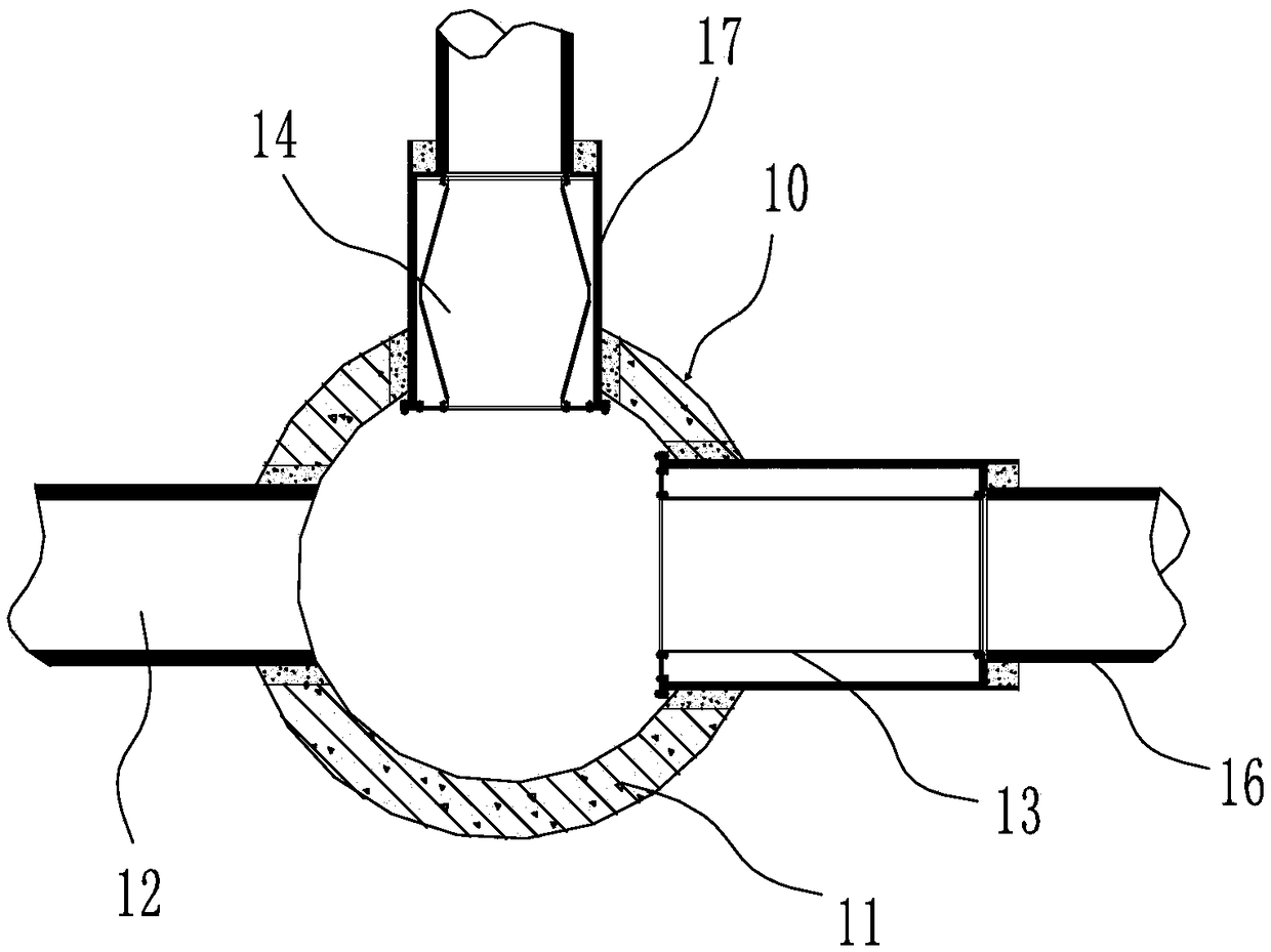
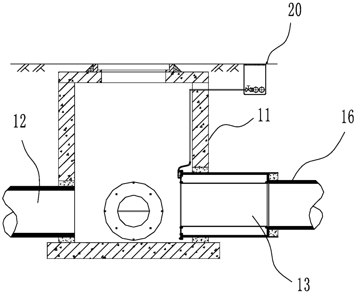
[0064] see figure 1 , figure 2 As shown, an embodiment of the present invention provides a flow control system for a diverter well, including: a compressed gas source, a gas delivery pipe, a control valve 20, a liquid level gauge 30 outside the well, a liquid level gauge 31 in the well, a pneumatic diverter well 10 and monitoring device.

[0065] The pneumatic diversion well 10 comprises a diversion well body 11 and a pneumatic shut-off device,

[0066] The form of the diversion well 10 in the present embodiment is form one:

[0067] The diversion well body is provided with a water inlet 12 and two water outlets, which are respectively the first water outlet and the second water outlet. The first water outlet is connected to the natural water body or the rainwater pipe through the first outlet pipe 16, and the second water outlet is connected to the natural water body or the rainwater pipe through the first water outlet. Two outlet pipes 17 are connected with sewage pipes ...

Embodiment 3

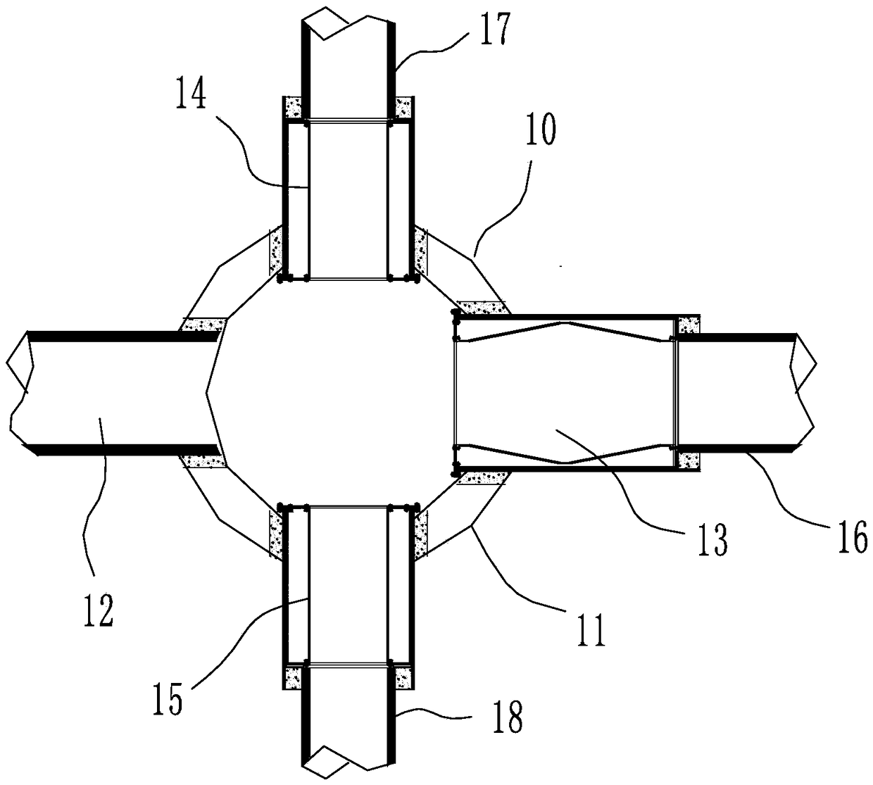
[0076] see image 3 , Figure 4 , Figure 5 As shown, the difference between embodiment 3 and embodiment 2 is: the form of the diversion well 10 is form three, the diversion well body 11 also includes a third water outlet, and the first water outlet communicates with the rainwater pipe or natural water body through the first outlet pipe 16 , the second water outlet pipe 17 is connected to the sewage pipe, storage tank or sewage treatment facility through the second water outlet pipe 17, and the third water outlet is connected to the initial rain pipe or the initial rainwater treatment facility through the third water outlet pipe 18,

[0077] The form of the diversion well 10 is form four, and the first water outlet pipe 16, the second water outlet pipe 17 and the third water outlet pipe 18 are respectively provided with a first pneumatic shut-off device 13, a second pneumatic shut-off device 14, and a third pneumatic shut-off device 15 . Three main pipes can be set, and the...


PUM


Abstract

The invention discloses a flow control method for a diversion shaft. A predetermined flow value is set, a flow value of a second water outlet pipe is measured as a real-time measured value, and the real-time measured value is compared with the predetermined flow value. When the real-time measured value is greater than the predetermined flow value, a controller issues a control signal to drive a control valve to actuate a pneumatic shut-off device to inflate, the second water outlet pipe tends to be closed until the measured value is equal to the predetermined flow value, and then the pneumaticshut-off device stops inflation. When the real-time measured value is smaller than the predetermined flow value, the controller issues a control signal to drive the control valve to actuate the pneumatic shut-off device to deflate, the second water outlet pipe tends to be opened until the measured value is equal to the predetermined flow value, and then the pneumatic shut-off device stops deflation.

Description

technical field [0001] The invention relates to the field of municipal engineering, in particular to a flow control method and a control system for a diversion well. Background technique [0002] At present, in the diversion well, abandonment well and interception well system, the system is composed of water inlet pipe, water outlet pipe and sewage intercepting pipe, which divert the domestic sewage in the drainage pipe or the initial rainwater and later rainwater, among which the domestic sewage Or the initial rainwater is intercepted to the sewage pipe and then transported to the sewage treatment plant for treatment and discharged after reaching the standard (further, the initial rainwater can be stored or intercepted to the sewage treatment plant for treatment and discharged after reaching the standard), and the middle and late rainwater is directly discharged into the natural water body . [0003] In reality, whether it is a rainwater pipe of a diversion system or a sew...

Claims


Application Information

Patent Timeline
Patent Type & Authority Applications(China)
IPC IPC(8): E03F1/00E03F5/10
CPCE03F1/00E03F5/10E03F5/101E03F5/105E03F5/107E03F2201/00
Inventor 李习洪周超
Owner WUHAN SHENGYU DRAINING SYST
Why Eureka
Try Eureka