Splicing device

A technology of splicing device and connecting plate, which is applied in the direction of identification device, pivot connection, instrument, etc., can solve the problem that arc connecting plate and screw cannot achieve fast arc splicing, etc., and achieve the effect of reliable splicing accuracy.

Pending Publication Date: 2019-02-22
SHENZHEN AOTO ELECTRONICS
View PDF0 Cites 0 Cited by
  • Summary
  • Abstract
  • Description
  • Claims
  • Application Information

AI Technical Summary

Problems solved by technology

[0003] Based on this, it is necessary to provide a splicing device for the problem that the arc connecting plate and the screw cannot realize fast arc splicing

Method used


Image

  • Splicing device
  • Splicing device
  • Splicing device

Examples


Embodiment Construction

[0026] In order to facilitate the understanding of the present invention, the present invention will be described more fully below with reference to the associated drawings. Preferred embodiments of the invention are shown in the accompanying drawings. However, the present invention can be embodied in many different forms and is not limited to the embodiments described herein. On the contrary, the purpose of providing these embodiments is to make the disclosure of the present invention more thorough and comprehensive.

[0027] It should be noted that when an element is referred to as being “fixed” to another element, it can be directly on the other element or there can also be an intervening element. When an element is referred to as being "connected to" another element, it can be directly connected to the other element or intervening elements may also be present. The terms "vertical," "horizontal," "left," "right," and similar expressions are used herein for purposes of ill...


PUM


Abstract

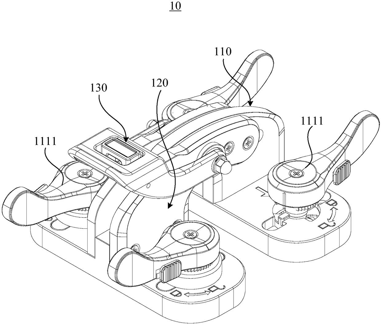
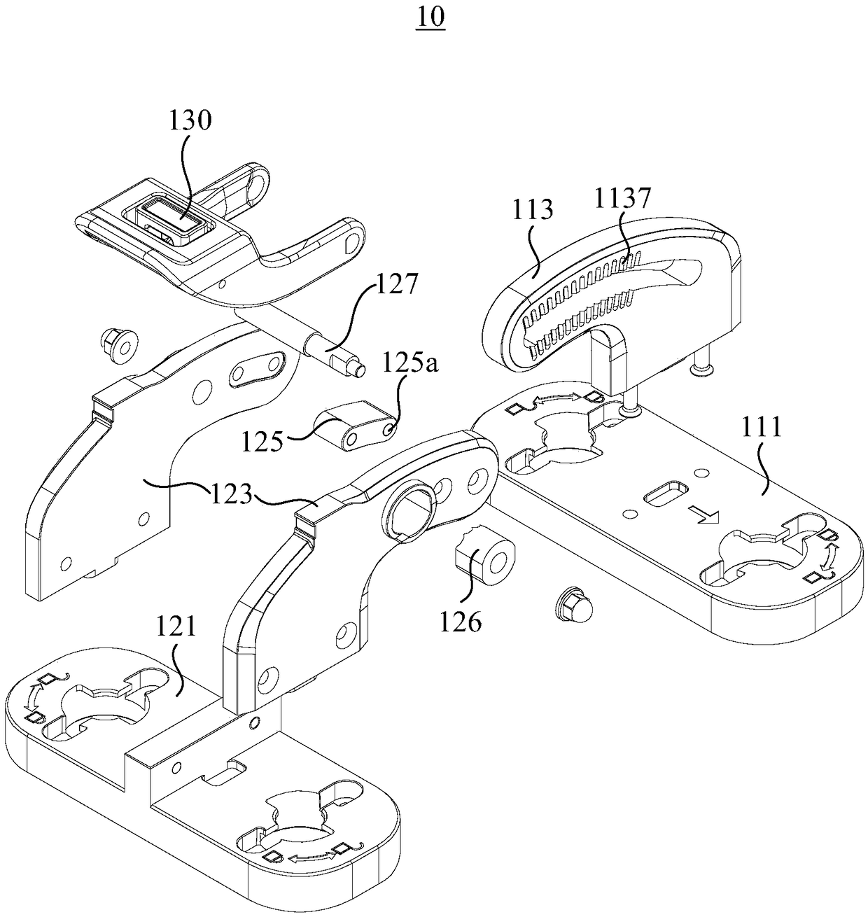
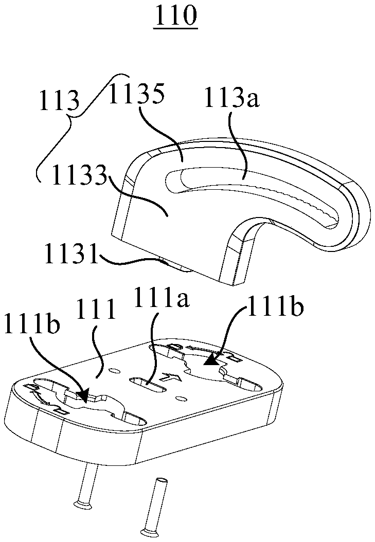
The invention relates to a splicing device. The splicing device comprises a first assembly, a second assembly and a handle assembly, wherein the first assembly comprises a first base and a first connecting plate; the first connecting plate is fixedly connected to the first base; a tooth tank is arranged on the first connecting plate; the second assembly comprises a second base, two second connecting plates and a clamping part; the two second connecting plates are fixedly connected to the second base and are arranged at intervals; at least part of the first connecting part is contained betweenthe two second connecting plates; the first connecting plate can slide relative to the second connecting plates; the clamping part is arranged on one of the two second connecting plates, and can relatively move toward a direction close to or far away from the first connecting plate so as to be meshed with the tooth tank or be demeshed with the tooth tank; the handle assembly comprises a handle which is rotatably connected to the second assembly; and in the rotating process of the handle, the clamping part is driven to move toward a direction close to or far away from the first connecting plate. The splicing device can realize the splicing of two LED (Light Emitting Diode) display units at different angles.

Description

technical field [0001] The invention relates to the field of LED display screens, in particular to a splicing device. Background technique [0002] The current LED display is generally formed by splicing multiple display units or display unit cabinets. With the advancement of technology and the expansion of application fields, LED display screens are no longer limited to the flat splicing of unit boxes, and more are beginning to require the ability to achieve curved splicing or wave splicing and other special-shaped splicing methods. Especially for the LED display used in the rental field, it is required to be easy, fast, stable and reliable to operate. To achieve the angle splicing of the display screen, it must be realized with the help of angle locks or arc connecting plates and screws. Curved connecting plates and screws can only be connected at a fixed angle, and the operation is time-consuming and laborious. It is not suitable for the field of rental display screens ...

Claims


Application Information

Patent Timeline
IPC IPC(8): F16C11/10G09F9/302
CPCG09F9/3026F16C11/103
Inventor 张翼翔肖华勇何昆鹏吴振志吴涵渠
Owner SHENZHEN AOTO ELECTRONICS
Why Eureka
Try Eureka