An ordinary electric valve realizes automatic high-precision adjustment control system
What is Al technical title?
Al technical title is built by PatSnap Al team. It summarizes the technical point description of the patent document.
A technology of regulating control, electric valve
Active Publication Date: 2020-09-29
安徽正刚新能源科技有限公司
View PDF11 Cites 0 Cited by
Summary
Abstract
Description
Claims
Application Information
AI Technical Summary
This helps you quickly interpret patents by identifying the three key elements:
Problems solved by technology
Method used
Benefits of technology
Problems solved by technology
[0004] What the present invention is to overcome is that electric control valves on the market are regulated by 4 to 20MA or 0 to 5V or 0-10V, which cannot achieve high-precision millisecond-level regulation, and the regulation accuracy is limited, and the existing PLC or DCS system cannot output 0.1 % High-precision analog signals cannot achieve high-precision control. The purpose is to provide a common electric valve to achieve automatic high-precision adjustment control system
Method used
Image
Click on the blue label to locate the original text in one second.
Reading with bidirectional positioning of images and text.
Examples
Embodiment 1
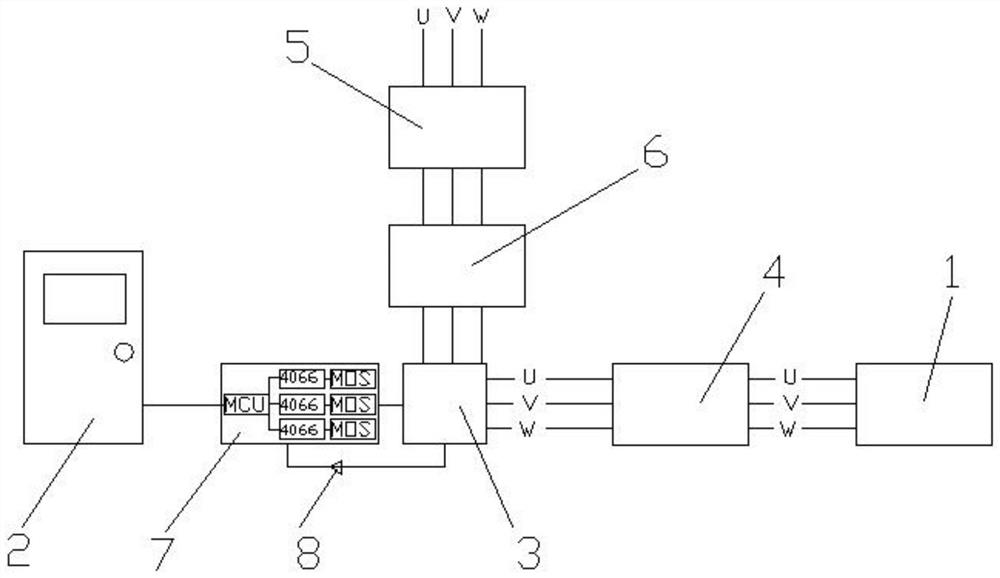
[0024] Such as figure 1 As shown; an ordinary electric valve realizes automatic high-precision adjustment control system, which is applied to a cold and hot continuous supply system, and is characterized in that it includes:
[0025] The electric valve 1, the electric valve 1 is installed in the cooling and heating continuous supply system, and the temperature sensor, pressure sensor and flow sensor are respectively installed in the cooling and heating continuous supply system,
[0026] DCS control cabinet 2, the temperature sensor, pressure sensor and flow sensor are respectively electrically connected to the input terminals of the DCS control cabinet,
[0027] Relay 3, electric valve 1 is connected to the output circuit of relay 3, and the input circuit of relay 3 is connected to the output terminal of DCS control cabinet 2,
[0028] A circuit protection module 4 is electrically connected between the connection between the electric valve 1 and the relay 3, and the output ci...
Embodiment 2
[0038] Such as figure 1 As shown; an ordinary electric valve realizes automatic high-precision adjustment control system, which is applied to a cold and hot continuous supply system, and is characterized in that it includes:
[0039] The electric valve 1, the electric valve 1 is installed in the cooling and heating continuous supply system, and the temperature sensor, pressure sensor and flow sensor are respectively installed in the cooling and heating continuous supply system,
[0040] DCS control cabinet 2, the temperature sensor, pressure sensor and flow sensor are respectively electrically connected to the input terminals of the DCS control cabinet,
[0041] Relay 3, electric valve 1 is connected to the output circuit of relay 3, and the input circuit of relay 3 is connected to the output terminal of DCS control cabinet 2,
[0042] A circuit protection module 4 is electrically connected between the connection between the electric valve 1 and the relay 3, and the output ci...
PUM
Abstract
The invention discloses an automatic high-precision adjustment control system for a common electric valve, and the automatic high-precision adjustment control system is applied to a cold and hot continuous supply system. The control system comprises an electric valve, a DCS control cabinet and a relay, wherein the electric valve is installed inside the cold and hot continuous supply system, and atemperature sensor, a pressure sensor and a flow sensor are installed inside the cold and hot continuous supply system separately; the temperature sensor, the pressure sensor and the flow sensor are electrically connected to the input end of the DCS control cabinet separately; and the electric valve is connected in an output loop of the relay, an input loop of the relay is connected with the output end of the DCS control cabinet, and a voltage reduction module and a frequency conversion module are electrically connected in the output loop of the relay. A 380 V / 50 HZ three-phase voltage input is adopted, 380 V three-phase voltage is converted into 110 V three-phase voltage through the voltage reduction module, and then the frequency is converted to 2 HZ through the frequency conversion module;, and a millisecond-level control unit is electrically connected between the relay and the DCS control cabinet.
Description
technical field [0001] The invention relates to the field of energy equipment, in particular to an automatic high-precision adjustment control system for an ordinary electric valve. Background technique [0002] Combined cooling and heating system, the compressor compresses the refrigerant to circulate among the air cooler, evaporator, and regenerator, and at the same time, it can realize cooling and heating. [0003] Electric valves are installed in traditional combined cooling and heating systems to control the input of CO2 inside the system. In order to realize the automatic control of electric valves, PLC or DCS systems are usually used to control the opening or closing of electric valves. Electric control valves on the market are used for 4 To 20MA or 0 to 5V or 0-10V adjustment, it is impossible to achieve high-precision millisecond-level adjustment, and the adjustment accuracy is limited, and the existing PLC or DCS system cannot output 0.1% high-precision analog sign...
Claims
Application Information
Patent Timeline
Application Date:The date an application was filed.
Publication Date:The date a patent or application was officially published.
First Publication Date:The earliest publication date of a patent with the same application number.
Issue Date:Publication date of the patent grant document.
PCT Entry Date:The Entry date of PCT National Phase.
Estimated Expiry Date:The statutory expiry date of a patent right according to the Patent Law, and it is the longest term of protection that the patent right can achieve without the termination of the patent right due to other reasons(Term extension factor has been taken into account ).
Invalid Date:Actual expiry date is based on effective date or publication date of legal transaction data of invalid patent.
