Floor brush and cleaning vacuum cleaner thereof

A rolling brush and scraper technology, applied in the direction of suction nozzles, etc., can solve problems such as low work efficiency, poor user experience, and inability to completely absorb sewage, and achieve the effect of thorough water absorption and high cleaning efficiency.

Pending Publication Date: 2019-02-26
TINECO APPLIANCES CO LTD
View PDF0 Cites 12 Cited by
  • Summary
  • Abstract
  • Description
  • Claims
  • Application Information

AI Technical Summary

Problems solved by technology

The sewage left by the roller brush on the back side when cleaning the ground needs to be sucked by the air duct when the floor brush moves backward, but cannot completely suck the sewage when the floor brush moves forward
In this way, the user is forced to push and pull the floor brush back and forth to achieve the purpose of cleaning the ground, which greatly reduces the efficiency of cleaning the ground and recycling sewage.
At the same time, some products set the clean water outlet and the roller brush chamber separately, and spray water from the front end to the rear end of the ground for cleaning. This also requires the user to move the brush back and forth continuously, so that the roller brush uses the clean water sprayed from the front end to clean the ground. , not only is the work efficiency low, but also leaves a bad user experience for the user

Method used


Image

  • Floor brush and cleaning vacuum cleaner thereof
  • Floor brush and cleaning vacuum cleaner thereof
  • Floor brush and cleaning vacuum cleaner thereof

Examples


Embodiment Construction

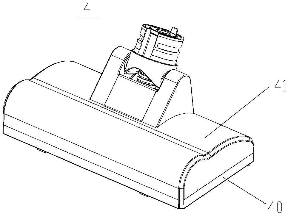
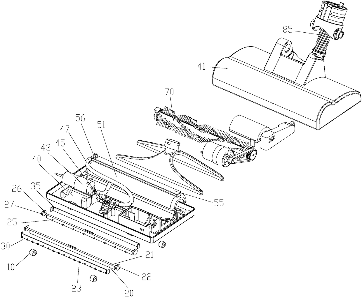
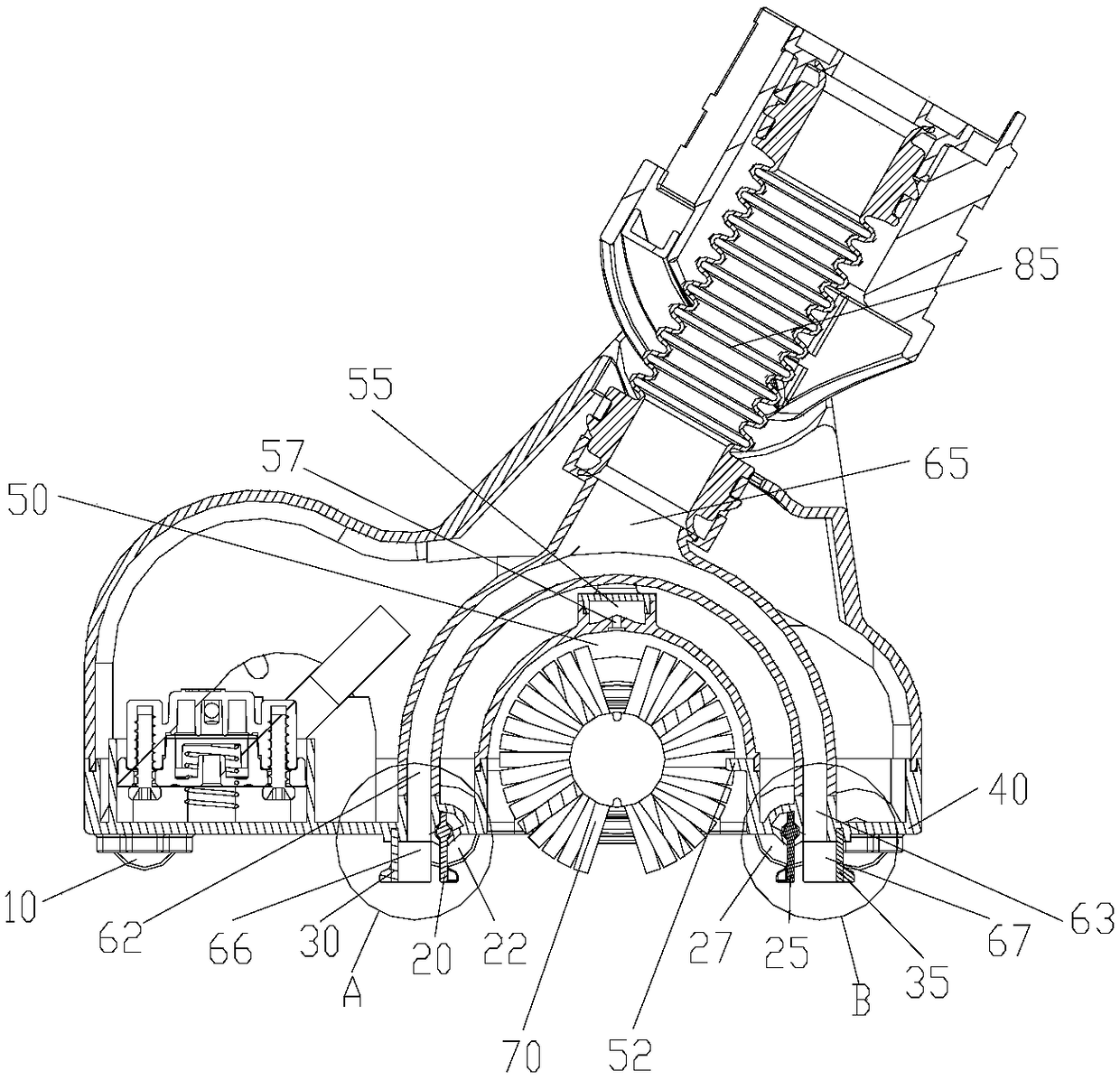
[0028] figure 1 It is a schematic diagram of the overall structure of the ground brush of the present invention; figure 2 Create an explosion map for the present invention; image 3 It is a sectional view of the ground brush of the present invention; Figure 4 for image 3 The enlarged view of the local structure of A; Figure 5 for image 3 The enlarged view of the local structure of B; Figure 6 It is a schematic diagram of the structure of the bottom surface of the brush of the present invention. combine Figure 1 to Figure 6 As shown, the present invention provides a floor brush, including a floor brush body 4 formed by fastening a floor brush base 40 and a cover 41, a rolling brush 70 is arranged in the floor brush body, and an air inlet is provided on the floor brush base. The rolling brush 70 is arranged in the rolling brush cavity 50, and the rolling brush cavity 50 is formed by buckling the rolling brush cover plate 51 and the ground brush base 40; the bottom ...


PUM


Abstract

The invention provides a floor brush and a cleaning vacuum cleaner thereof. The floor brush comprises a floor brush body (4) which is fastened by a floor brush base (40) and a surface cover (41), a roller brush (70) is arranged inside, an air inlet is formed in the floor brush base, the floor brush body is provided with an air duct, the beginning end of the air duct faces the air inlet, the end isconnected with a hose (85), the air inlet includes a front air inlet (66) and a rear air inlet (67) on the front and rear sides respectively of the roller brush, the air duct is correspondingly arranged as a front air duct (62) and a rear air duct (63), the front air inlet and the rear air inlet are respectively provided with reversible scraper assemblies, under the action of turning over the scraper assemblies, when the floor brush advances, the front air duct is the main air duct, and the rear air duct is the secondary air duct; when the floor brush is retreated, the rear air duct is the main air duct, and the front air duct is the secondary air duct. The cleaner utilizes the double air ducts to cooperate with the scraper assemblies so that the floor brush can move in one direction onlyin the working process, and the ground can be left without stains at one time, thereby achieving the functions of high-efficiency water absorption and cleaning.

Description

technical field [0001] The invention relates to a floor brush and a cleaning vacuum cleaner thereof, belonging to the technical field of small household appliances. Background technique [0002] As a unique category of floor brushes for vacuum cleaners, cleaning and vacuuming brushes have the function of cleaning the floor and sucking up sewage at the same time. In the prior art, the cleaning floor brush air duct and the roller brush are arranged independently of each other to form a front-rear positional relationship. Most products on the market set the air inlet on the front side of the floor brush, and the roller brush on the back side of the air inlet. The sewage left when the roller brush at the rear side cleans the ground needs to be sucked by the air duct when the floor brush moves backwards, but cannot completely suck the sewage when it moves forward. In this way, the user is forced to push and pull the ground brush back and forth to achieve the purpose of cleaning...

Claims


Application Information

Patent Timeline
IPC IPC(8): A47L9/04
CPCA47L9/04
Inventor 张志伟任怀强刘凯
Owner TINECO APPLIANCES CO LTD
Why Eureka
Try Eureka