Rope winder

A winding machine and rope technology, applied in the direction of conveying filamentous materials, thin material processing, transportation and packaging, etc., can solve the problems of concentrated winding of ropes in one place, lack of dust removal mechanism in winders, etc. Good roll quality, high winding automation coefficient, and compact structure

Active Publication Date: 2019-02-26
山东丰航绳业有限公司
View PDF12 Cites 6 Cited by
  • Summary
  • Abstract
  • Description
  • Claims
  • Application Information

AI Technical Summary

Problems solved by technology

[0003] The object of the present invention is to provide a rope winding machine in order to solve the above problems, which solves the problem that the existing rope winding machine rotates and winds the ropes to be wound in a certain place, and the existing winding machine The problem of lack of dust removal mechanism

Method used


Image

  • Rope winder
  • Rope winder
  • Rope winder

Examples


Embodiment Construction

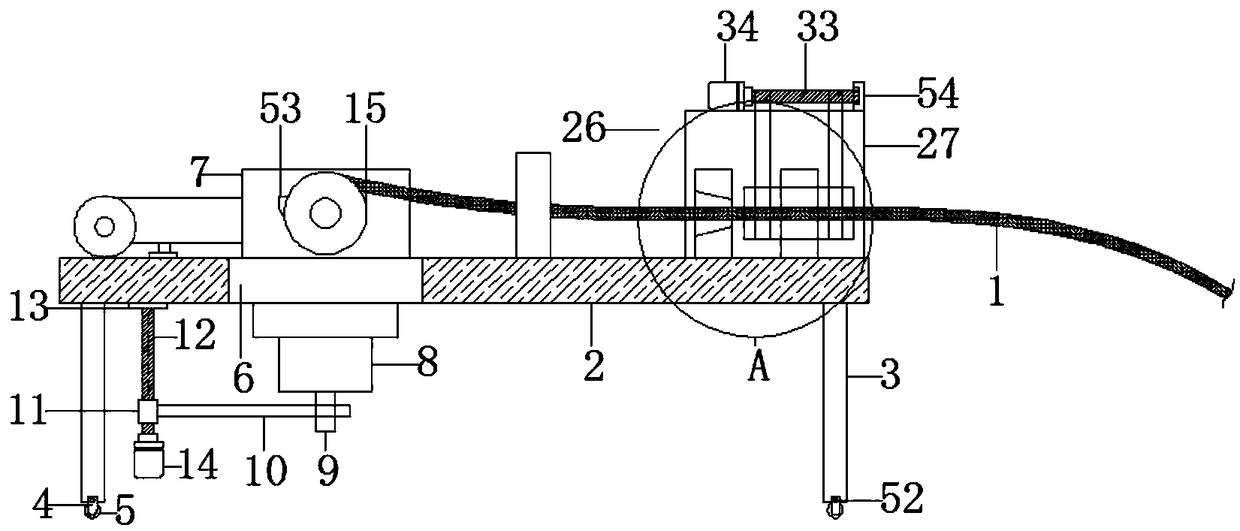
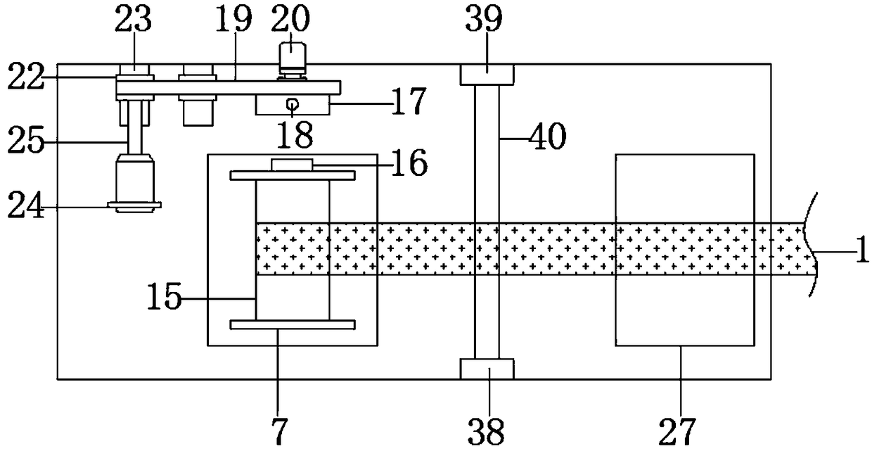
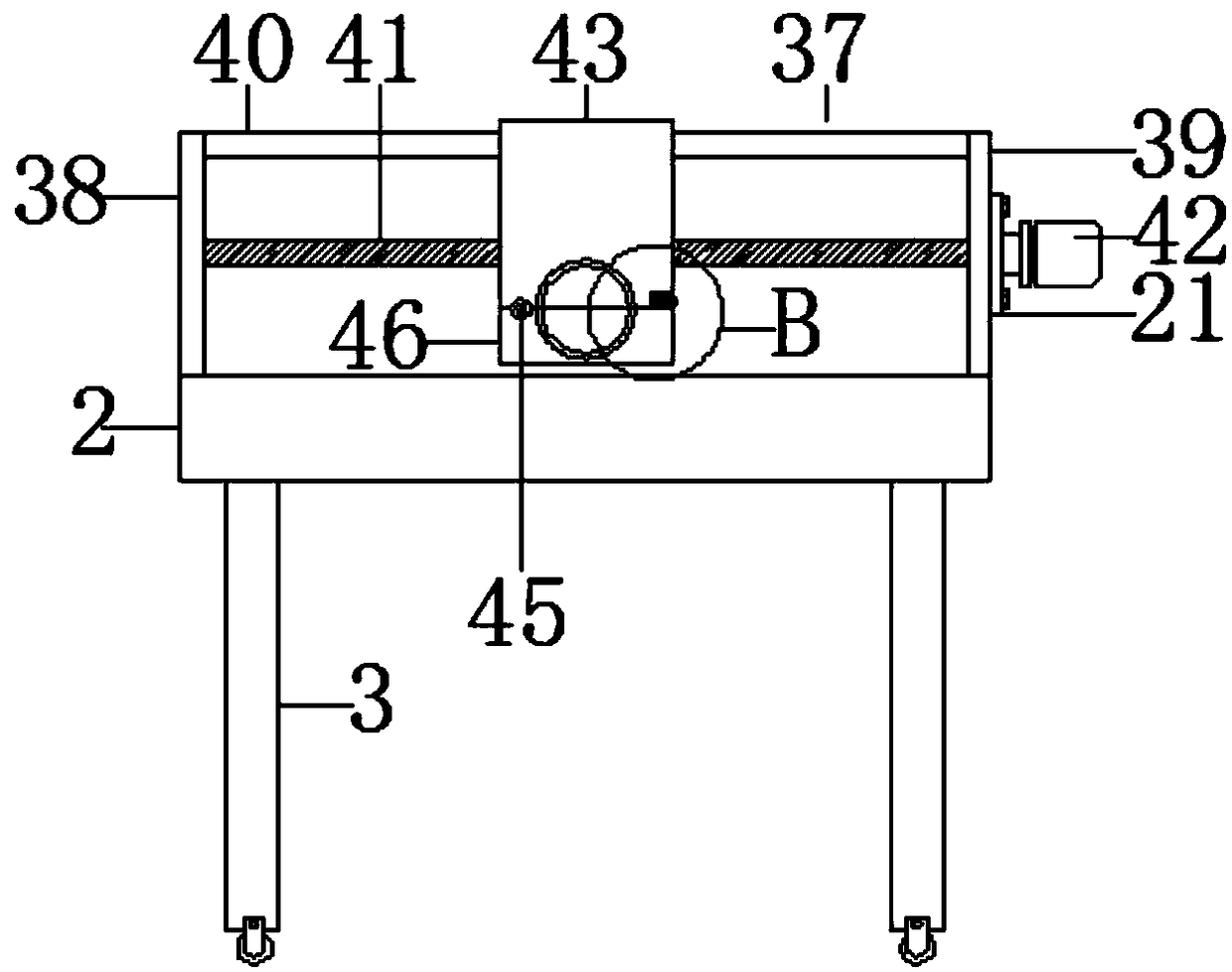
[0022] Such as Figure 1-6 As shown, this specific embodiment adopts the following technical solutions: a rope winding machine, comprising a rope 1 and a winding platform 2, characterized in that four support columns 3 are arranged below the winding platform 2, and the bottom ends of the support columns 3 are The moving wheel 5 is connected with the connecting frame 4, and the winding platform 2 is provided with a winding platform gap 6, and the winding platform gap 6 is provided with a winding frame 7, and the winding frame 7 is made as a U-shaped structure, and the winding frame 7 The lower end is fixedly connected with the transmission frame 8, the bottom end of the transmission frame 8 is connected with the transmission rod 10 through the transmission shaft 9, the other end of the transmission rod 10 is connected with the moving block 11, the moving block 11 is sleeved on the threaded rod 12, and the upper end of the threaded rod 12 is connected In the bearing seat 13 on t...


PUM


Abstract

The invention discloses a rope winder which comprises a rope and a winding table. Four supporting columns are arranged on the lower side of the winding table. The bottom ends of the supporting columnsare connected with movable wheels through connecting frames. A winding table notch is formed in the winding table and internally provided with a winding frame. The winding frame is of a U-type structure. The lower end of the winding frame is fixedly connected with a transmission frame. The bottom end of the transmission frame is connected with a transmission rod through a transmission shaft. Theother end of the transmission rod is connected with a movable block. A threaded rod is sleeved with the movable block. The upper end of the threaded rod is connected into a bearing pedestal of the lower end face of the winding table. The lower end of the threaded rod is connected with a first rotating motor. The threaded rod penetrates through the movable block. The threaded rod is in threaded connection with the movable block. A winding roller is erected on the winding frame. The two ends of the winding roller penetrate through the winding frame. By arranging a rope surface dust removal mechanism and a rope swinging mechanism, the rope can be more conveniently and simply wound and can be more conveniently stored and replaced after being wound.

Description

Technical field: [0001] The invention relates to a winding machine, in particular to a rope winding machine. Background technique: [0002] With the continuous diversification of market demand, more and more products are being innovated to meet the diversified and changing market demand, and the rope winding machine is the same. Most of the existing rope winding adopts a simple winding roller to rotate and wind. However, this kind of rotating winding will cause the rope to be wound up in one place of the winding roller, resulting in a limited length of the rope wound by the winding roller, and the existing winding machine is not equipped with a dust removal mechanism on the surface of the rope, making the winding Most of the rolled ropes have windings, which affect the quality of winding. Invention content: [0003] The object of the present invention is to provide a rope winding machine in order to solve the above problems, which solves the problem that the existing rope...

Claims


Application Information

Patent Timeline
Patent Type & Authority Applications(China)
IPC IPC(8): B65H54/28B65H54/553B65H54/70
CPCB65H54/28B65H54/553B65H54/702B65H2701/35
Inventor 孙钰涵
Owner 山东丰航绳业有限公司
Why Eureka
Try Eureka