Cable pay-off device for 5G communication laying

A pay-off device and cable technology, applied in the direction of cable laying equipment, etc., can solve the problems of the influence of the service life of the protective layer, uneven pressure distribution, heavy weight of cables and cable racks, etc.

Pending Publication Date: 2022-08-09
浙江邮电职业技术学院
View PDF0 Cites 0 Cited by
  • Summary
  • Abstract
  • Description
  • Claims
  • Application Information

AI Technical Summary

Problems solved by technology

[0002] Existing cables are usually rolled on the cable rack after production, and then the cable rack (with the cable rolled) is transported to the location that needs to be installed or replaced, and finally the cable is taken up or released, but often the cable and the cable The weight of the frame is relatively large, and it has high requirements on th

Method used


Image

  • Cable pay-off device for 5G communication laying
  • Cable pay-off device for 5G communication laying
  • Cable pay-off device for 5G communication laying

Examples


Example Embodiment

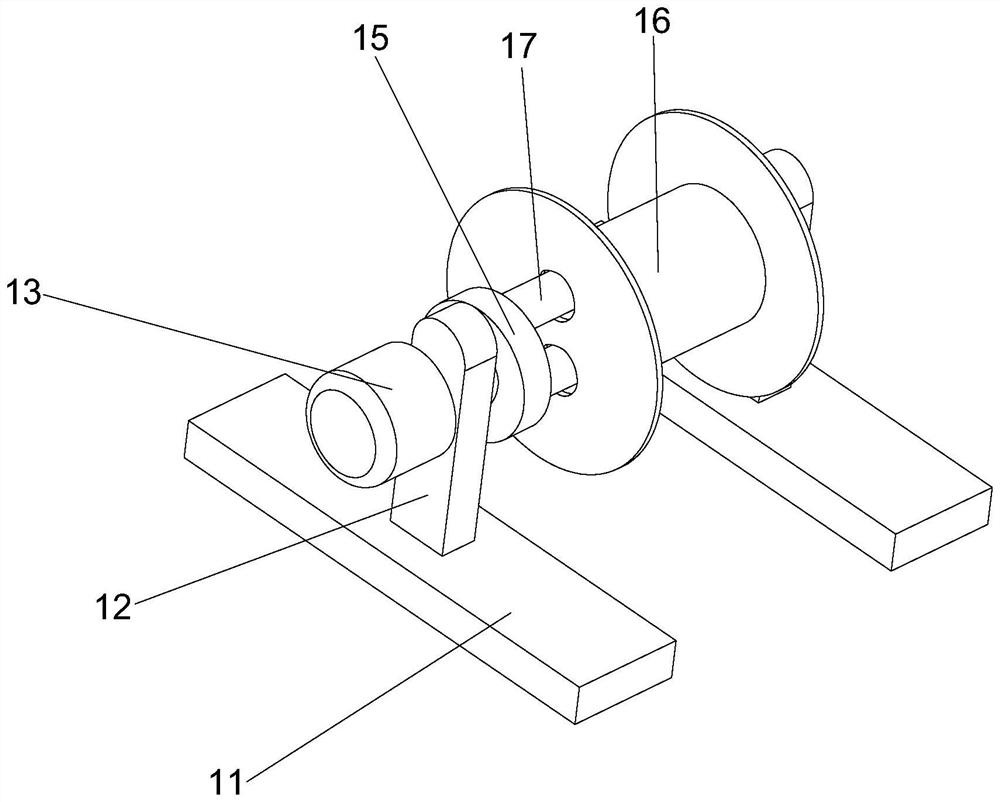
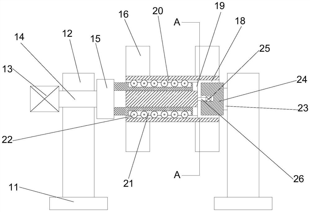
[0022] Embodiments of the present invention provide a cable pay-off device for 5G communication laying, such as Figure 1-4 As shown in the figure, it includes two sets of bases 11, cable pay-off racks 16, two sets of rotary forks 17, driven turntables 24 and translation drive mechanisms. The upper sides of the two sets of bases 11 are fixedly installed with brackets 12, and the cable pay-off racks 16 are placed in the Between the two brackets 12, one of the brackets 12 is provided with a drive motor 13 on the side away from the cable pay-off rack 16. The output end of the drive motor 13 is powered with a power shaft 14. The power shaft 14 extends through the bracket 12 to the bracket 12 close to the cable release On the side of the wire rack 16, the power rotating shaft 14 is fixedly connected to the side of the cable pay-off frame 16 with a rotating disk 15, and two sets of rotating forks 17 are fixedly connected to the side of the rotating disk 15 close to the cable pay-off ...


PUM


Abstract

The invention provides a cable pay-off device for 5G communication laying, the cable pay-off device comprises two bases, a cable pay-off rack, two rotating forks, a driven turntable and a translation driving mechanism, brackets are fixedly mounted on the upper sides of the two bases, and the cable pay-off rack is placed between the two brackets; wherein a driving motor is arranged on the side, away from the cable pay-off rack, of one support, the output end of the driving motor is in power connection with a power rotating shaft, the power rotating shaft penetrates through the supports and extends to the side, close to the cable pay-off rack, of the supports, and a rotating disc is fixedly connected to the side, close to the cable pay-off rack, of the power rotating shaft. According to the scheme, the cable pay-off rack axially slides back and forth along the rotating fork, so that the withdrawn cable is positioned in the take-up area of the cable pay-off rack for horizontal wiring, and the situation that the cable and a protective layer on the outer side of the cable are damaged due to concentrated winding and non-uniform pressure distribution of the outer side of the cable in a unit space is prevented.

Description

technical field [0001] The invention relates to the technical field of communication construction equipment, in particular to a cable release device for 5G communication laying. Background technique [0002] Existing cables are usually rolled on cable racks after production, and then the cable racks (rolled with cables) are transported to the location that needs to be installed or replaced, and finally the cables are taken up or paid off, but often cables and cables. The weight of the rack is relatively large, which has high requirements on the compressive capacity of the cable and the cable protective layer, and the cost is high. Once the cable outside the unit space is concentratedly wound during the cable storage process, the pressure distribution is uneven, and it is easy to damage the cable and the cable. The service life of the protective layer on the outside of the cable is affected. SUMMARY OF THE INVENTION [0003] (1) Technical problems solved [0004] In view ...

Claims


Application Information

Patent Timeline
IPC IPC(8): B65H75/44B65H75/38H02G1/06
CPCB65H75/4413B65H75/38H02G1/06B65H2701/34
Inventor 徐鑫校
Owner 浙江邮电职业技术学院
Why Eureka
Try Eureka