A reel line flattening device

A technology of a wire pressing device and a reel, which is applied in the direction of a hoisting device, a spring mechanism, etc., can solve the problem that a rope guiding mechanism cannot guide the rope, and achieves the effects of avoiding damage and damage, low cost, and preventing concentrated winding.

Active Publication Date: 2015-07-29
HUAQIANG FANGTE WUHU CULTURE TECH CO LTD
View PDF7 Cites 0 Cited by
  • Summary
  • Abstract
  • Description
  • Claims
  • Application Information

AI Technical Summary

Problems solved by technology

However, the two ends of the guide shaft are all fixed on the flanges on both sides of the rope reel, and the flanges do not rotate with the rope reel. situation, the rope guide mechanism will not be able to realize the function of guiding the rope

Method used


Image

  • A reel line flattening device
  • A reel line flattening device
  • A reel line flattening device

Examples


Embodiment Construction

[0018] In order to make the technical means, creative features, goals and effects achieved by the present invention easy to understand, the present invention will be further described below in conjunction with specific illustrations.

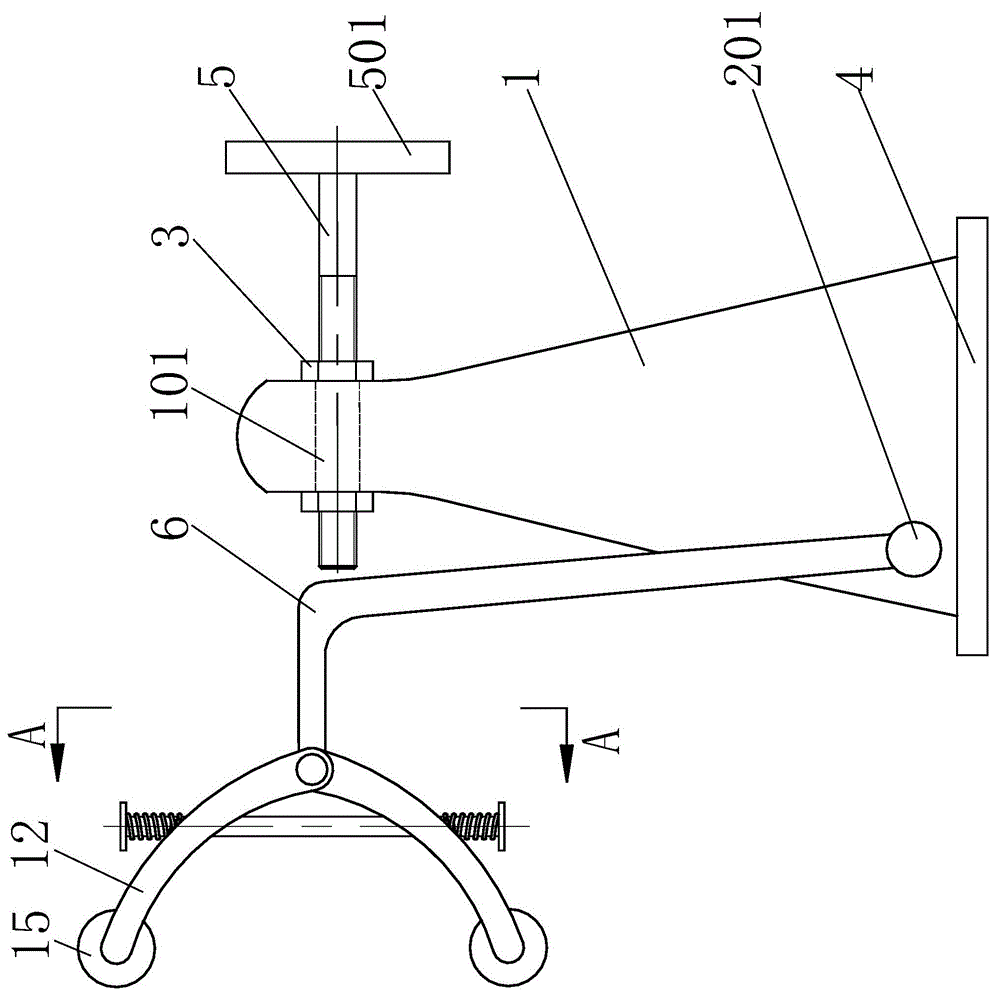
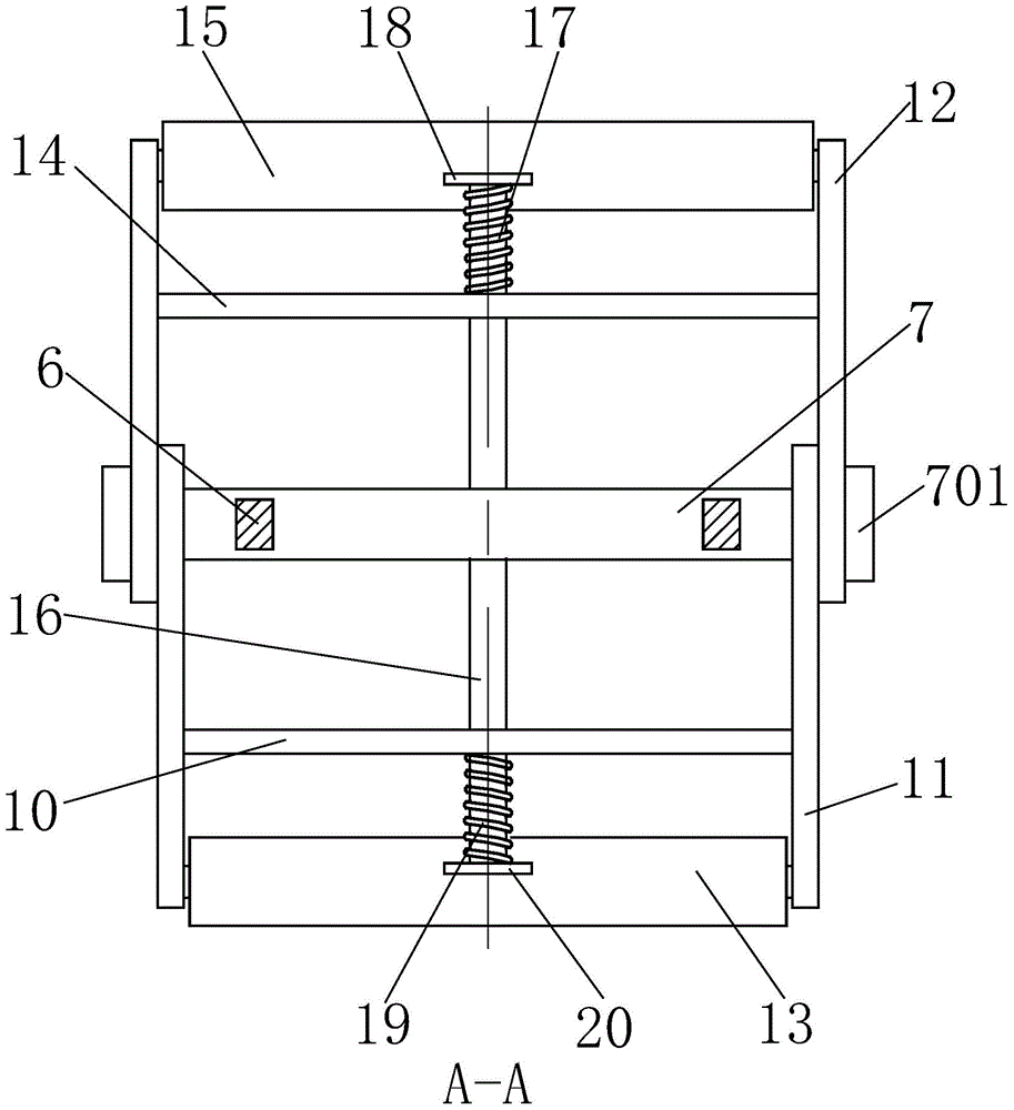
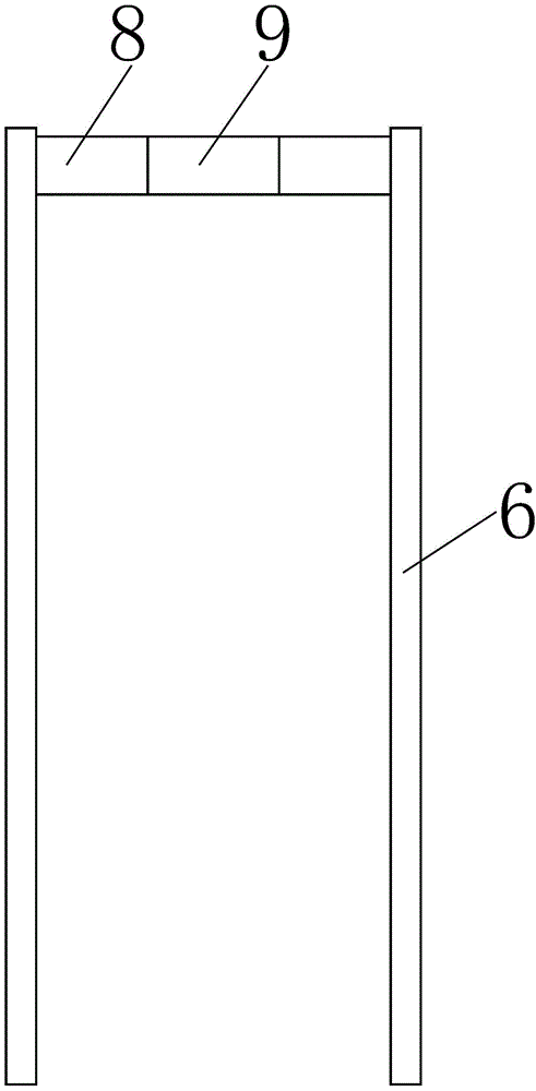
[0019] Such as Figure 1 to Figure 7 As shown, a reel line flattening device includes a crimping device, a supporting device and a fastening device, the crimping device includes a support shaft 7, the supporting device includes a support frame 1, and the fastening device includes a screw thread Rod 5, the middle part of the support shaft 7 is symmetrically welded with a compression frame 6, and the welding point is located at the upper left end of the compression frame 6, the welding connection method is simple to connect, and the strength of the connected part is guaranteed, because the welded part It does not need to be disassembled, so it is more appropriate to adopt welding. The two ends of the support shaft 7 are symmetrically sleeved with ...


PUM


Abstract

The invention relates to a coiling block wire flattening device which comprises a supporting shaft, a supporting frame and a threaded rod. Compressing frames are symmetrically arranged in the middle of the supporting shaft in a welded mode, lower compressing arms are arranged on the two end portions of the supporting shaft in a sleeved mode, upper compressing arms are arranged on the two end portions of the supporting shaft in a sleeved mode, a lower limiting crossbeam is welded between the lower compressing arms, and lower compressing wheels are installed at the left ends of the lower compressing arms. An upper limiting crossbeam is welded between the upper compressing arms, and upper compressing wheels are installed at the left ends of the upper compressing arms. A vertical limiting rod is arranged in the middle of the upper limiting crossbeam and the middle of the lower limiting crossbeam, the vertical limiting rod is sleeved with an upper limiting spring and a lower limiting spring, a rotary shaft is arranged on the lower portion of the supporting frame and the rotary shaft is sleeved with the compressing frames. A compressing crossbeam is fixed between the compressing frames. A crosswise through hole is formed in the upper portion of the supporting frame and nuts are fixed to the two ends of the crosswise through hole. The coiling block wire flattening device can effectively prevent ropes from being wound in a concentrated mode and prevent the ropes from jumping or sliding laterally, guarantee the safety of a pulled object and avoid damage to related equipment.

Description

technical field [0001] The invention relates to the technical field of winding equipment, in particular to a winding wire flattening device. Background technique [0002] In the process of rewinding and unwinding the steel wire rope or steel cable, one end is generally wound on the drum, and the rotation of the drum is used to control the tightening or loosening of the steel cable. However, during the rotation of the reel, since the position of the steel cable wound on the reel generally does not actively change, the steel cables on the reel often appear to be wound on the same position of the reel, which will be damaged over time. The steel cable causes a certain amount of wear, which reduces the strength of the cable. On the other hand, there is a certain gap in the middle of the concentratedly wound steel cable. In the process of further tensioning the steel cable, the steel cable will jump or slide sideways, that is, a certain section of steel cable will slip from the o...

Claims


Application Information

Patent Timeline
Patent Type & Authority Patents(China)
IPC IPC(8): B66D1/38
Inventor 陈祖尧易伟林
Owner HUAQIANG FANGTE WUHU CULTURE TECH CO LTD
Why Eureka
Try Eureka