A rotor copper wire winding device for a rotating electrical machine

A technology for rotating electrical machines and rotor copper, used in electromechanical devices, manufacturing motor generators, electrical components, etc., can solve the problems of poor copper wire winding effect, uneven copper wire winding, and a lot of dust on copper wire, etc. Quality and efficiency, achieve the effect of winding, improve the effect of dust removal

Active Publication Date: 2019-02-15
FOSHAN YIFA ELECTRICAL TECH
View PDF6 Cites 0 Cited by
  • Summary
  • Abstract
  • Description
  • Claims
  • Application Information

AI Technical Summary

Problems solved by technology

[0003] In the manufacturing process of rotating electrical machines, the winding of the copper wire of the motor rotor is one of the most important production processes. At present, the copper wire wound on the work frame is manually wound on the iron core of the rotor; this The disadvantages of this method of manually winding copper wires are: not only the labor intensity of workers is high, the efficiency of winding is low, but also winding devices are used for winding, but the existing winding devices have poor winding effects on copper wires. Copper wires cannot be evenly wound on the rotor core, and a large amount of dust is easily attached to the copper wires wound on the iron core during the winding process, which in turn affects the normal production process of the rotor. Therefore, it is urgent to provide a rotor for rotating electrical machines. Copper wire winding device to achieve uniform winding of the copper wire of the rotor core and remove the dust attached to the copper wire during the winding process

Method used


Image

  • A rotor copper wire winding device for a rotating electrical machine
  • A rotor copper wire winding device for a rotating electrical machine

Examples


Embodiment Construction

[0016] Below in conjunction with specific embodiment, the technical scheme of this patent is described in further detail:

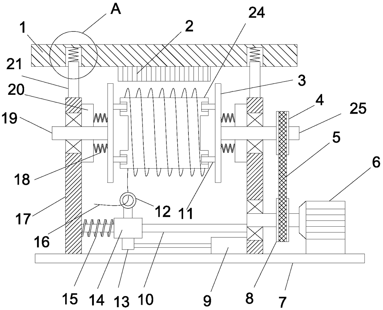
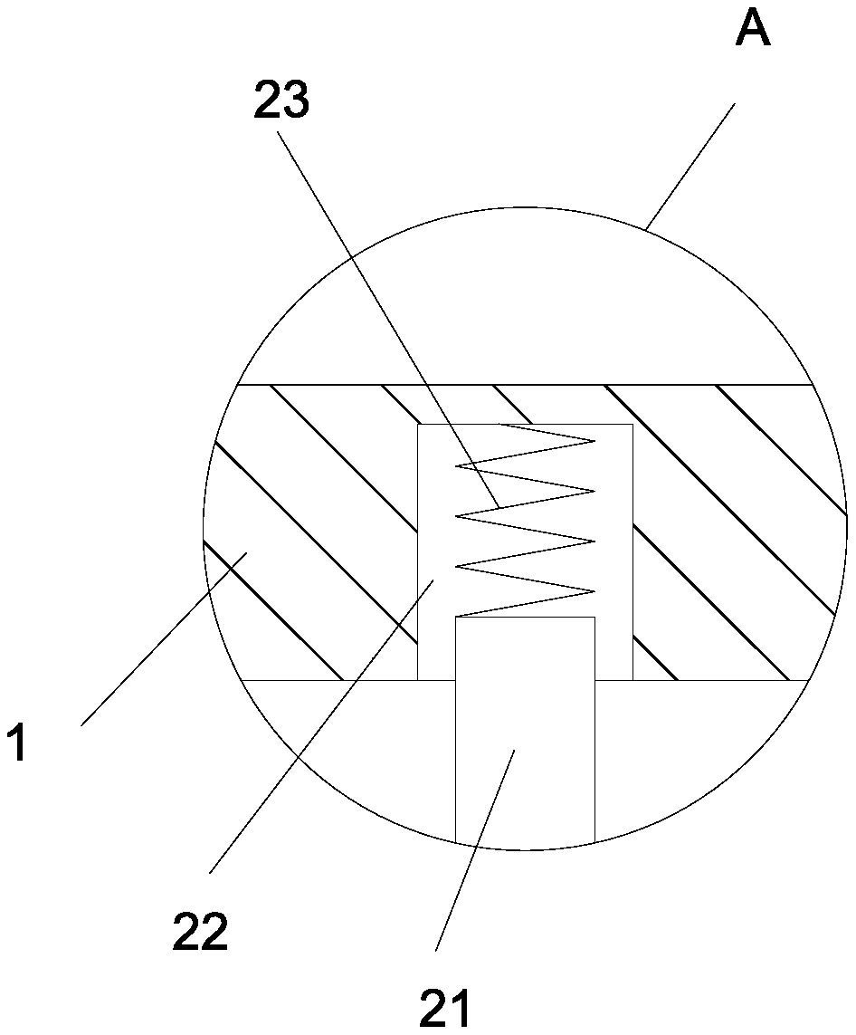
[0017] see Figure 1-2 , a rotor copper wire winding device for a rotating electrical machine, comprising a base plate 7, two vertical plates 17 are welded and fixed on the base plate 7, and the two vertical plates 17 are evenly perpendicular to the base plate 7; each of the vertical plates On the plate 17, a buffer shaft 21 is vertically fixedly installed, a top plate 1 is arranged above the vertical plate 17, and a dust removal brush 2 is provided on the bottom surface of the top plate 1; The buffer shaft 21 is slidably embedded in the limit chute 22, the second limit spring 23 is arranged in the limit chute 22, the upper end of the second limit spring 23 is fixed on the top plate 1, and the second limit spring The lower end of 23 is fixed on the buffer shaft 21; the first connecting shaft 19 and the second connecting shaft 25 are respectively horizont...


PUM


Abstract

The invention discloses a rotor copper wire winding device for a rotary motor. The device comprises a base plate; two vertical plates are welded and fixedly mounted on the base plate; a lower end of a second limiting spring is fixed on a buffer shaft; the two vertical plates are respectively equipped with a first connection shaft and a second connection shaft in a horizontal rotation mode; shaft sleeves are fixedly mounted at the inner sides of the two vertical plates. The first connection rods and the second connection rods penetrate the shaft sleeves in a sliding mode. Fixing plates are vertically and fixedly mounted on the first connection rods and the second connection rods. A driven pulley and a drive pulley are in drive connection through a drive belt. A limiting rod is horizontally and fixedly mounted between the two vertical plates. According to the device, a slide sleeve is driven by a telescopic hydraulic cylinder to carry out horizontal reciprocating slide along the limiting rod and further a limiting ring is driven to carry out left and right reciprocating motion, so a winding position of a copper wire on a rotor iron core is changed; the copper wire is prevented from being centrally wound at certain position of the iron core; a uniform winding effect is realized; and the copper wire winding quality and efficiency are improved.

Description

technical field [0001] The invention relates to the technical field of motor production and manufacturing, in particular to a rotor copper wire winding device for a rotating electrical machine. Background technique [0002] There are two types of rotating electrical machines, DC motors and AC motors, and AC motors are divided into synchronous motors and asynchronous motors, and synchronous motors can be divided into synchronous generators and synchronous motors. Asynchronous motors can be divided into three-phase asynchronous motors and single-phase asynchronous motors according to the number of phases; according to their different rotor structures, they can be divided into cage-type and wound-rotor types. Among them, cage-type three-phase asynchronous motors are simple in structure and easy to manufacture. Convenience, cheap price, reliable operation, the most widely used in various motors, the largest demand. [0003] In the manufacturing process of rotating electrical ma...

Claims


Application Information

Patent Timeline
Patent Type & Authority Patents(China)
IPC IPC(8): H02K15/08
CPCH02K15/08
Inventor 肖路长
Owner FOSHAN YIFA ELECTRICAL TECH
Why Eureka
Try Eureka