Induction cooker and state detection method and control method thereof

An induction cooker and pot cover technology, which is applied to household appliances, household stoves/stoves, electric heating fuels, etc., can solve the problem that the pot cover is not on the pot body, etc., and achieves the effect of convenient operation, not easy to misjudgment, and accurate control.

Active Publication Date: 2020-02-07
ZHEJIANG SHAOXING SUPOR DOMESTIC ELECTRICAL APPLIANCE CO LTD
View PDF5 Cites 0 Cited by
  • Summary
  • Abstract
  • Description
  • Claims
  • Application Information

AI Technical Summary

Problems solved by technology

[0005] In order to solve at least one problem related to the misjudgment that the pot cover is not on the pot body during the cooking process of the induction cooker mentioned in the background technology, the present invention provides an induction cooker cooker and a detection method and a control method for the state of the pot cover

Method used


Image

  • Induction cooker and state detection method and control method thereof
  • Induction cooker and state detection method and control method thereof
  • Induction cooker and state detection method and control method thereof

Examples


Embodiment 1

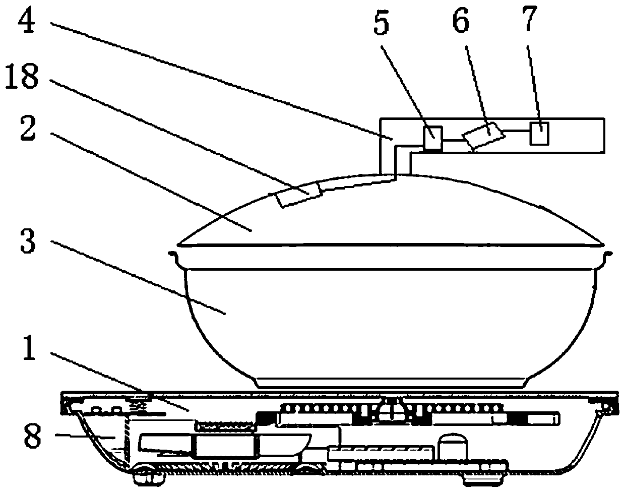
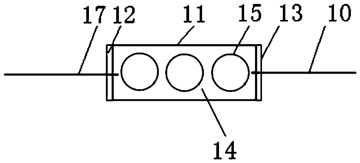
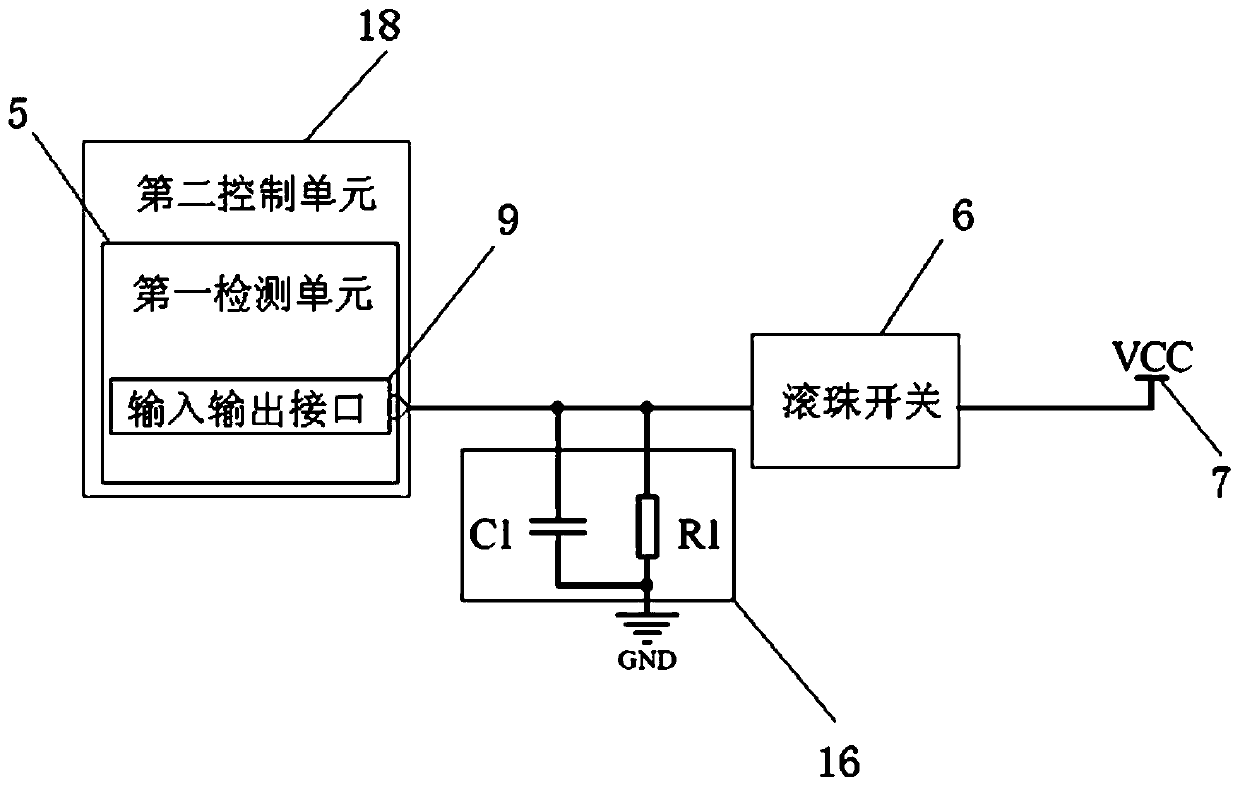
[0061] figure 1 It is a structural schematic diagram of an induction cooker provided in Embodiment 1 of the present invention; figure 2 It is a structural schematic diagram of a ball switch in an induction cooker provided in Embodiment 1 of the present invention; image 3 It is a connection diagram of a first detection unit, a second detection unit, a ball switch, a power supply and a filter circuit in an electromagnetic cooker provided by Embodiment 1 of the present invention. Such as Figure 1-Figure 3 As shown, the induction cooker provided in this embodiment includes: an induction cooker 1 and a pot, the induction cooker 1 is provided with a first control unit, and the cooker includes a pot body 3 and a pot cover 2,

[0062] The induction cooker also includes: a first detection unit 5 and a second control unit 18 electrically connected to the first detection unit 5;

[0063] The pot cover 2 has a supporting part, which is used to support the pot cover 2 when the pot co...

Embodiment 2

[0102] Figure 4 It is a schematic flow chart of a method for detecting the state of a pot lid in an induction cooker provided by Embodiment 2 of the present invention. Figure 5 It is a schematic flowchart of another method for detecting the state of a pot lid in an induction cooker provided by Embodiment 2 of the present invention. The method for detecting the state of a pot lid in an induction cooker provided in this embodiment is applied to a scene of cooking food with an induction cooker.

[0103] Specifically, the induction cooker 1 and the cooker, the first control unit is arranged in the induction cooker 1, the cooker includes a pot body 3 and a pot cover 2, and the cooker for the induction cooker also includes: a first detection unit 5 and a first detection unit 5 electrically connected The second control unit 18; the pot cover 2 has a support portion, and the support portion is used to support the pot cover 2 when the pot cover 2 is placed vertically. The lid handl...

Embodiment 3

[0129] Figure 7 It is a schematic flow chart of a control method for an induction cooker provided in Embodiment 3 of the present invention; Figure 8 It is a schematic flow chart of another control method for an induction cooker provided in Embodiment 3 of the present invention; Figure 9 It is a schematic flowchart of a control method for an induction cooker provided by Embodiment 3 of the present invention. Specifically, such as Figure 7 As shown, the control method of the induction cooker cooker provided in this embodiment includes:

[0130] S401. Detect the input value of the input and output interface 9. The input value of the input and output interface 9 changes with the position of the ball switch 6; if the input value of the input and output interface 9 is less than or equal to the first preset threshold, Step 402 is executed, and if the input value of the input / output interface 9 is greater than the first preset threshold, step 403 is executed.

[0131] S402. Wh...


PUM


Abstract

The invention provides an electromagnetic cooker and a method for detecting and controlling the state of a pot cover thereof. The electromagnetic oven cooker of the present invention comprises: a first detection unit and a second control unit electrically connected to the first detection unit; There is a ball switch and a power supply connected to the ball switch, and the ball switch is electrically connected to the first detection unit; the first detection unit has an input and output interface connected to the ball switch. The electromagnetic cooker provided by the invention is easy to operate for detecting the state of the pot cover, is not prone to misjudgment, and can accurately control the cooking process.

Description

technical field [0001] The invention relates to the field of household appliances, in particular to an electromagnetic cooker and a detection method and a control method for the state of the pot cover thereof. Background technique [0002] With the continuous improvement of people's living standards, induction cooker cookers have become a widely used cooking utensils. Induction cookers are electric cooking utensils made using the principle of electromagnetic induction heating. It is composed of ferromagnetic material pot bottom cookware and other parts. When in use, an alternating current is passed into the coil plate, and an alternating magnetic field is generated around the coil. Most of the magnetic force lines of the alternating magnetic field pass through the metal pot body, and a large amount of eddy current is generated in the bottom of the pot. , thereby generating the heat required for cooking. [0003] At present, the method of judging the position of the precise ...

Claims


Application Information

Patent Timeline
Patent Type & Authority Patents(China)
IPC IPC(8): F24C7/08A47J36/06
CPCA47J36/06F24C7/082
Inventor 周宇
Owner ZHEJIANG SHAOXING SUPOR DOMESTIC ELECTRICAL APPLIANCE CO LTD
Why Eureka
Try Eureka