Dish delivery cart
The technology of a dining car and a frame is applied in the field of dining cars, which can solve the problems of slow meal delivery, cold meals, and high labor intensity, and achieve the effects of ensuring meal quality, improving meal speed, and reducing work intensity.
- Summary
- Abstract
- Description
- Claims
- Application Information
AI Technical Summary
Problems solved by technology
Method used
Image
Examples
Embodiment 1
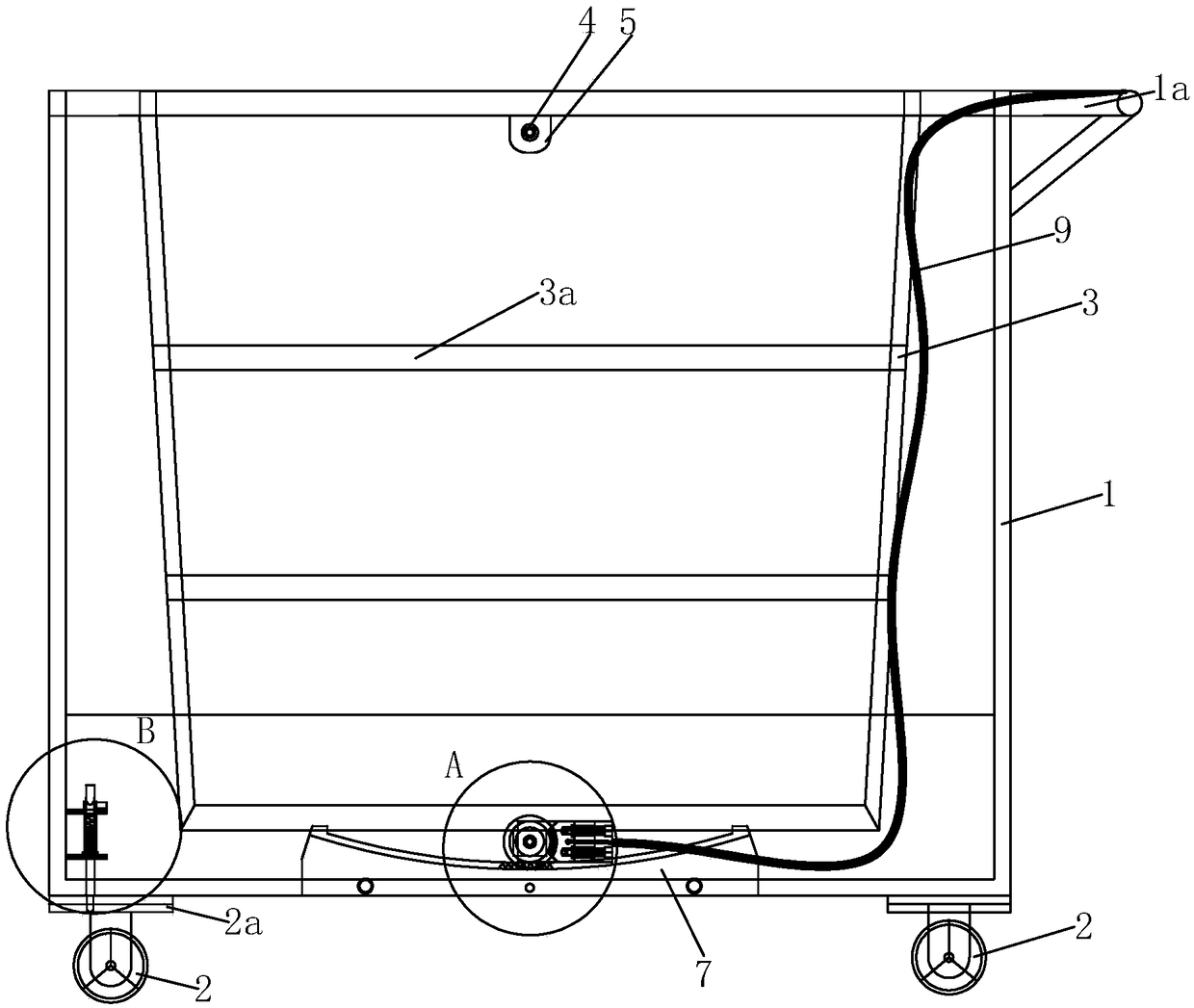
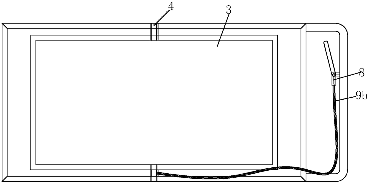
[0036] Such as Figure 1-5 , a dining car, mainly by the vehicle frame 1 and a gear locking mechanism and so on. Wherein, the vehicle frame 1 is a rectangular frame structure, and is preferably welded and formed by stainless steel. The vehicle frame 1 has four uprights, and these four uprights are located on the four vertices of the same rectangle, and the upper and lower ends of the adjacent two uprights They are respectively connected by beams and longitudinal beams, and the beams and longitudinal beams are welded and fixed to the columns. The four corners of the bottom of the vehicle frame 1 are equipped with a universal wheel 2 respectively, and the vehicle frame 1 is supported on the ground by the four universal wheels 2 and moves.
[0037] A wheel orientation assembly is provided between the two universal wheels 2 on the front side and the vehicle frame 1, which can make the two universal wheels 2 on the front side switch between universal wheels and one-way wheels . ...
Embodiment 2
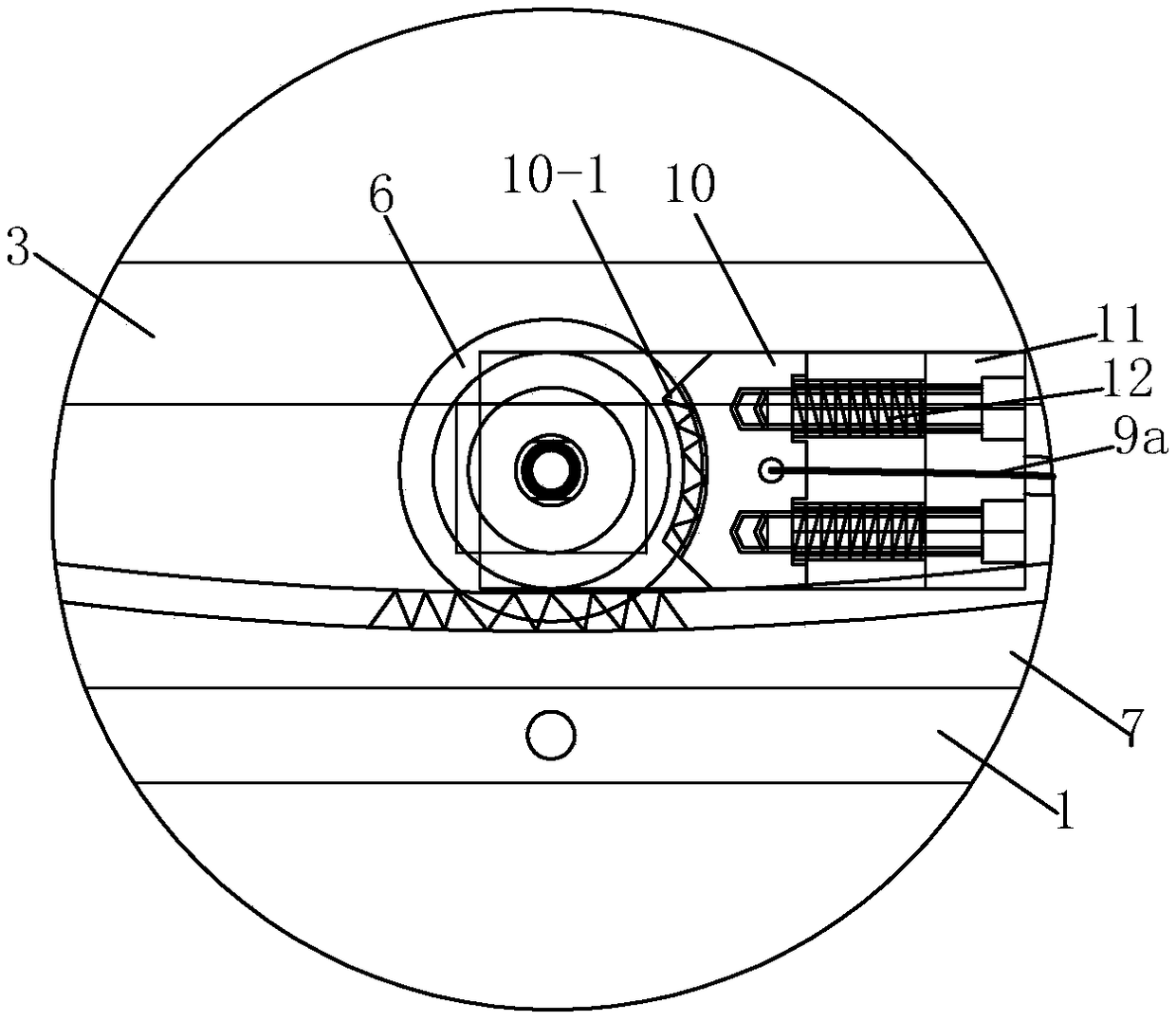
[0045] refer to Figure 1-5 , On the basis of Embodiment 1, this embodiment refines the gear locking mechanism. The control assembly 9 is preferably an externally purchased cable assembly, the cable 9a of the cable assembly is fixed to the back of the locking piece 10, and the locking block 10 is installed in the U-shaped block 11. The side of the locking block 10 is slidably matched with the inner walls of the two sections of the U-shaped block 11. The U-shaped block is fixedly installed on the vehicle frame 1 or the balance meal rack 3, and the back side of the locking piece 10 is connected to the connecting edge of the U-shaped block 11. A plurality of return springs 12 are arranged between them. One end of all back-moving springs 12 snaps in the groove on the connecting edge of U-shaped block 11, and the other end of back-moving spring 12 snaps in the groove on the back side of locking member 10. One end of the protective sheath 9 b of the cable assembly is fixed on the ...
Embodiment 3
[0047] refer to Figure 1-5 , and combined with Figure 6 with 7 It can be seen that, on the basis of Embodiment 1, this embodiment refines the gear locking mechanism. The control assembly 9 is preferably an outsourced cable assembly, and the cable 9a of the cable assembly is used to control an outsourced hoop brake assembly, and the two brake discs of the hoop brake are separated on both sides of the gear 6 , and can hold the gear 6 tightly so that the gear 6 cannot rotate. When the waiter's hands loosen or tighten the control handle 8, the control handle 8 makes the brake disc of the hoop brake assembly clamp or release the gear 6 through the control assembly 9, thereby selectively making the gear 6 not rotate or rotate. The rest of the structure of this embodiment is completely the same as that of Embodiment 1, and will not be repeated here.
PUM
 Abstract
Description
Claims
Application Information
 - R&D Engineer
- R&D Manager
- IP Professional
- Industry Leading Data Capabilities
- Powerful AI technology
- Patent DNA Extraction
Browse by: Latest US Patents, China's latest patents, Technical Efficacy Thesaurus, Application Domain, Technology Topic, Popular Technical Reports.
© 2024 PatSnap. All rights reserved.Legal|Privacy policy|Modern Slavery Act Transparency Statement|Sitemap|About US| Contact US: help@patsnap.com


