
Throttle device and air conditioner

A technology of throttling device and air conditioner, which is applied in the direction of fluid circulation arrangement, refrigerator, lighting and heating equipment, etc., can solve the problems of inability to adjust the throttling effect, affecting the operation of the air conditioner, and the valve core in the throttle valve being stuck, etc. Achieve the effect of enhancing commutation reliability, improving reliability and improving commutation efficiency

Active Publication Date: 2020-12-25
QINGDAO HAIER AIR CONDITIONER GENERAL CORP LTD +1
View PDF5 Cites 0 Cited by
  • Summary
  • Abstract
  • Description
  • Claims
  • Application Information

AI Technical Summary

Problems solved by technology

[0002] At present, in the prior art, the throttling device between the evaporator and the condenser of the air conditioner is generally a constant flow throttling element, such as a capillary tube and a throttle valve. These two throttling methods can only provide one throttle. The throttling effect cannot be adjusted according to the flow rate and the pressure changes on both sides. In the air conditioning system where the throttle valve is used as a throttling device, the throttle valve changes the throttling direction depending on the high and low pressure conversion of the system. In actual use, it is often The spool in the throttle valve is stuck, which affects the normal operation of the air conditioner

Method used


Image

  • Throttle device and air conditioner
  • Throttle device and air conditioner
  • Throttle device and air conditioner

Examples


Embodiment Construction

[0040] The following description and drawings illustrate specific embodiments of the invention sufficiently to enable those skilled in the art to practice them. Other embodiments may incorporate structural, logical, electrical, process, and other changes. The examples merely represent possible variations. Individual components and functions are optional unless explicitly required, and the order of operations may vary. Portions and features of some embodiments may be included in or substituted for those of other embodiments. The scope of embodiments of the present invention includes the full scope of the claims, and all available equivalents of the claims. Herein, various embodiments may be referred to individually or collectively by the term "invention", which is for convenience only and is not intended to automatically limit the scope of this application if in fact more than one invention is disclosed. A single invention or inventive concept. Herein, relational terms such...


PUM


Abstract

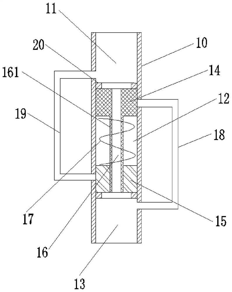
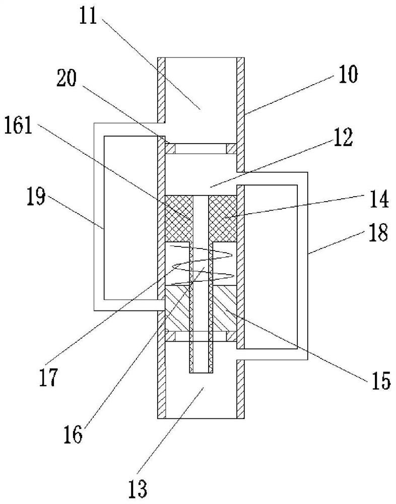
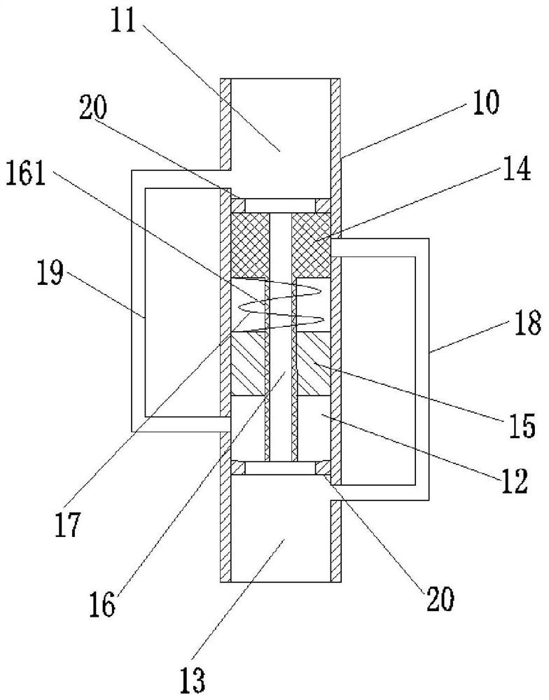
The invention discloses a throttling device and an air conditioner, which belong to the field of air conditioning. The throttling device includes a valve body, a first valve core, a second valve core and an elastic element; the valve body includes a first chamber, a second chamber and the third chamber, the first spool and the second spool are respectively slidably arranged in the second chamber; the elastic element is located between the first spool and the second spool, and the first spool and the second Through holes are respectively arranged on the valve core, and a refrigerant channel is arranged between the two through holes, and a bypass pipeline is arranged outside the valve body, and the bypass pipeline is used to connect the first chamber and the third chamber. When the first spool and the second spool are in the initial position, the bypass line is closed; when the pressure difference between the first chamber and the third chamber is greater than or equal to the preset value, the first spool is controlled. Moving downward, or the second spool moving upward, the elastic element is in a compressed state, and the bypass pipeline is in an open state. This solution solves the drawbacks that capillary tubes and throttle valves cannot adjust the flow rate.

Description

technical field [0001] The invention relates to the technical field of air conditioning, in particular to a throttling device and an air conditioner. Background technique [0002] At present, in the prior art, the throttling device between the evaporator and the condenser of the air conditioner is generally a constant flow throttling element, such as a capillary tube and a throttle valve. These two throttling methods can only provide one throttle. The throttling effect cannot be adjusted according to the flow rate and the pressure changes on both sides. In the air conditioning system where the throttle valve is used as a throttling device, the throttle valve changes the throttling direction depending on the high and low pressure conversion of the system. In actual use, it is often The valve core in the throttle valve is stuck, which affects the normal operation of the air conditioner. Contents of the invention [0003] Embodiments of the present invention provide a thrott...

Claims


Application Information

Patent Timeline
Patent Type & Authority Patents(China)
IPC IPC(8): F25B41/06F25B41/30
CPCF25B41/30
Inventor 徐明韩涛任德亮张振超
Owner QINGDAO HAIER AIR CONDITIONER GENERAL CORP LTD
Learn More