Pixel driving circuit and display device

A pixel driving circuit and driving module technology, applied in static indicators, instruments, etc., can solve the problems of incompatibility with different driving frequencies, manufacturing process deviation of driving transistors, uneven display of organic light-emitting display devices, etc., so as to avoid uneven display. Effect

Active Publication Date: 2019-03-01
YUNGU GUAN TECH CO LTD
View PDF5 Cites 12 Cited by
  • Summary
  • Abstract
  • Description
  • Claims
  • Application Information

AI Technical Summary

Problems solved by technology

[0002] Organic light-emitting display devices generally include several pixels, and each pixel includes a pixel driving circuit and an organic light-emitting structure. Currently, the commonly used pixel driving circuit is a 2T1C structure, that is, the pixel driving circuit includes two transistors and a storage capacitor, one of which The transistor is a switching transistor, and the other transistor is a driving transistor for driving the organic light-emitting structure to emit light. The driving current generated by the driving transistor for driving the organic light-emitting structure to emit light is related to the threshold voltage of the driving transistor, the threshold voltage drift of the driven transistor and the manufacturing process of the driving transistor Due to the influence of deviation, there is a problem of uneven display in organic light-emitting display devices
[0003] In addition, for different application scenarios, it is necessary to use different driving frequencies to drive the organic light-emitting display device to meet the needs of users for different driving frequencies, and it is also necessary to use different driving frequencies to drive the pixel driving circuits in the organic light-emitting display device, but currently Commonly used pixel drive circuits are difficult to be compatible with different drive frequencies

Method used


Image

  • Pixel driving circuit and display device
  • Pixel driving circuit and display device
  • Pixel driving circuit and display device

Examples


Embodiment Construction

[0040] The present invention will be further described in detail below in conjunction with the accompanying drawings and embodiments. It should be understood that the specific embodiments described here are only used to explain the present invention, but not to limit the present invention. In addition, it should be noted that, for the convenience of description, only some structures related to the present invention are shown in the drawings but not all structures. Throughout this specification, the same or similar reference numerals represent the same or similar structures, elements or processes. It should be noted that, in the case of no conflict, the embodiments in the present application and the features in the embodiments can be combined with each other.

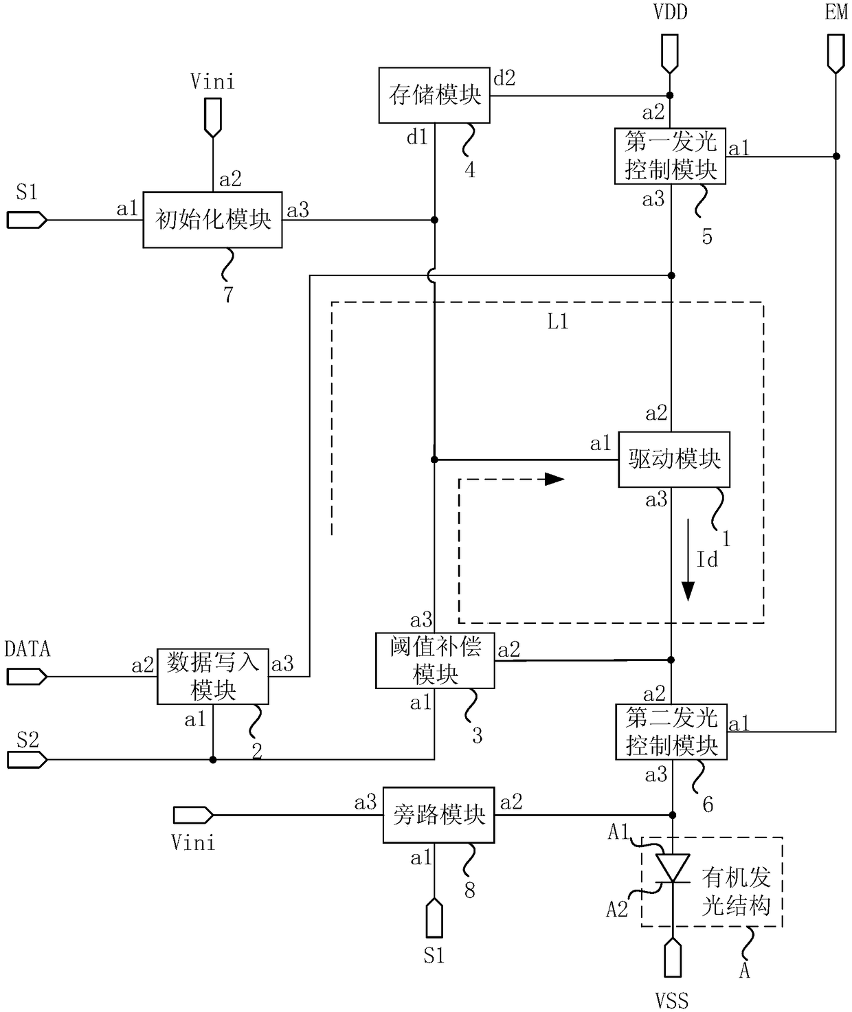
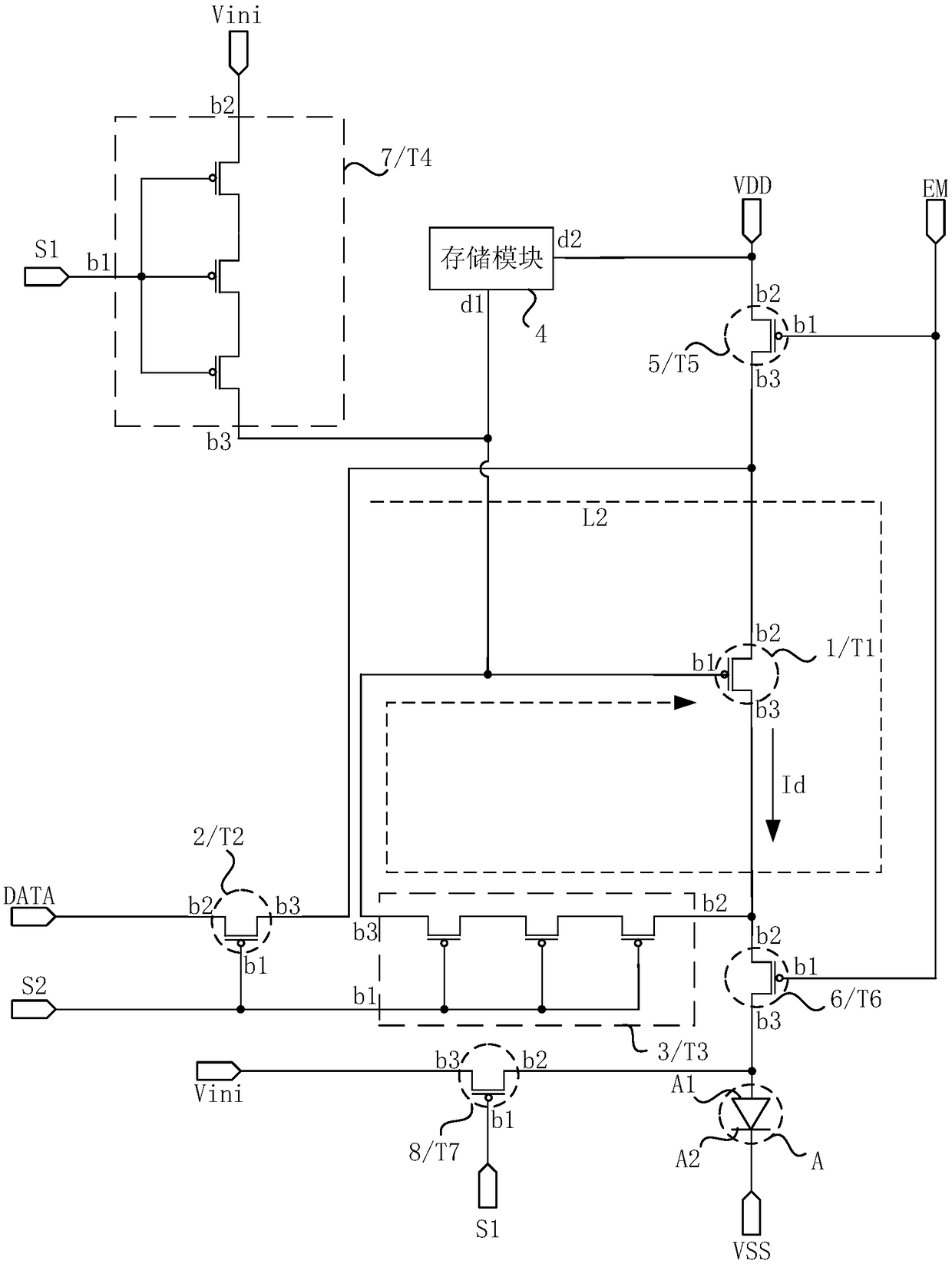
[0041] An embodiment of the present invention provides a pixel driving circuit, including a driving module, a data writing module, a threshold compensation module and a storage module, the driving module is used to prov...


PUM


Abstract

The invention discloses a pixel driving circuit and a display device. The pixel driving circuit comprises a driving module, a data write-in module, a threshold compensation module and a storage module, and the threshold compensation module writes a compensation signal including drive transistor threshold voltage information in the control end of the driving module before a light-emitting stage; the storage module maintains the voltage of the control terminal of the driving module in the light-emitting stage, and the storage module includes a plurality of first capacitor elements which are arranged in series; the capacitance of the storage module is set to be a first capacitance when the pixel driving circuit is driven at a first driving frequency, and the capacitance of the storage moduleis set to be a second capacitance when the pixel driving circuit is driven at a second driving frequency; and the first driving frequency is greater than the second driving frequency, and the first capacitance is smaller than the second capacitance. The above technical scheme effectively avoids the problem of display unevenness existing in the display device, so the pixel circuit can be compatiblewith different driving frequencies.

Description

technical field [0001] Embodiments of the present invention relate to the field of display technology, and in particular, to a pixel driving circuit and a display device. Background technique [0002] Organic light-emitting display devices generally include several pixels, and each pixel includes a pixel driving circuit and an organic light-emitting structure. Currently, the commonly used pixel driving circuit is a 2T1C structure, that is, the pixel driving circuit includes two transistors and a storage capacitor, one of which The transistor is a switching transistor, and the other transistor is a driving transistor for driving the organic light-emitting structure to emit light. The driving current generated by the driving transistor for driving the organic light-emitting structure to emit light is related to the threshold voltage of the driving transistor, the threshold voltage drift of the driven transistor and the manufacturing process of the driving transistor Due to the...

Claims


Application Information

Patent Timeline
Patent Type & Authority Applications(China)
IPC IPC(8): G09G3/3233G09G3/3266
CPCG09G3/3233G09G3/3266G09G2320/0233
Inventor 王龙彦范文志谢正芳朱晖
Owner YUNGU GUAN TECH CO LTD
Why Eureka
Try Eureka