Movable clamping type electronic connector

An electronic connector and clamping technology, which is applied in the field of movable clamping electronic connectors, can solve the problems of no backup opening and closing methods, inconvenient opening and closing of electronic devices, and inconvenient operation.

Inactive Publication Date: 2019-03-01
东台市高科技术创业园有限公司
View PDF5 Cites 4 Cited by
  • Summary
  • Abstract
  • Description
  • Claims
  • Application Information

AI Technical Summary

Problems solved by technology

However, the existing two conductors are usually butt-connected and conducted through threaded connection, and when an instant closing operation is required, the thread is rotated and unscrewed, which is very inconvenient to operate; in addition, when it is necessary to connect the two conductors When splitting and breaking the circuit, once the thread rusts and causes a dead connection, it will cause inconvenience to the opening and closing of the electronic device, and there is no backup opening and closing method

Method used


Image

  • Movable clamping type electronic connector

Examples


Embodiment Construction

[0015] The content of the present invention will be further described in detail below in conjunction with the accompanying drawings.

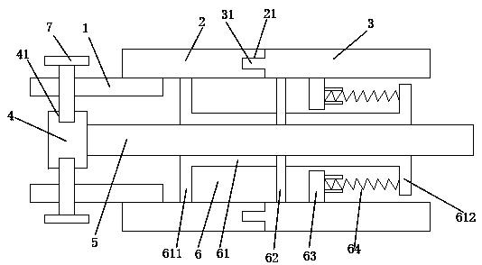
[0016] Such as figure 1 As shown, a movable clamping electronic connector includes a first connecting ring 1, a conducting block 4, a second connecting ring 2, a telescopic conducting rod 5, a spare opening and closing assembly 6, and a clamping screw 7; One end of the first connecting ring 1 is threaded inside one end of the second connecting ring 2; the conduction block 4 is fixedly installed in the first connecting ring 1; the spare opening and closing assembly 6 includes a pressing ring 3, The socket 61 and the connecting rod 62; the end-to-end movable pressing ring 3 presses against the other end of the second connecting ring 2; the socket 61 has a circular cylindrical structure; The insertion sleeve 61 is installed inside the second connection ring 2 and the pressure ring 3; one end of the insertion sleeve 61 is fixed inside the second c...


PUM


Abstract

The invention discloses a movable clamping type electronic connector. The movable clamping type electronic connector comprises a first connection ring, a breakover block, a second connection ring, a flexible breakover rod, a standby start/stop assembly and a clamping screw. The breakover block is clamped and connected in the first connection ring through the clamping screw, so that the operation is more convenient and rapid when the breakover needs to be dismounted for size change or overhauling.

Description

technical field [0001] The invention relates to a movable clamping type electronic connector. Background technique [0002] An electronic connector is a device that bridges and splits two conductors on a circuit so that current or signals can flow from one conductor to another conductor. However, the existing two conductors are usually butt-connected and conducted through threaded connection, and when an instant closing operation is required, the thread is rotated and unscrewed, which is very inconvenient to operate; in addition, when it is necessary to connect the two conductors When splitting and breaking the circuit, once the thread rusts and causes a dead connection, it will cause inconvenience to the opening and closing of the electronic device, and there is no backup opening and closing method. Contents of the invention [0003] In view of the deficiencies of the above-mentioned prior art, the problem to be solved by the present invention is: to provide a movable cl...

Claims


Application Information

Patent Timeline
Patent Type & Authority Applications(China)
IPC IPC(8): H01R11/01H01R4/38H01R4/48
CPCH01R4/38H01R4/4863H01R11/01
Inventor 朱亚云
Owner 东台市高科技术创业园有限公司
Why Eureka
Try Eureka