Aluminum liquid refining equipment

A technology of refining equipment and aluminum liquid, which is applied in the field of aluminum liquid refining equipment, can solve the problems of aluminum liquid disturbance, large bubbles, and burning of aluminum liquid, and achieve the effects of avoiding temperature loss, small bubbles, and reducing burning loss

Inactive Publication Date: 2019-03-05
SNTO TECH GRP
View PDF4 Cites 2 Cited by
  • Summary
  • Abstract
  • Description
  • Claims
  • Application Information

AI Technical Summary

Problems solved by technology

The disadvantage of this scheme is that 1) the bubbles of argon and nitrogen blown out by the steel pipe are large, and they rise up and run away without being fully mixed with the aluminum liquid, and the refining effect on the aluminum liquid is poor; 2) the argon and nitrogen blown out by the steel pipe are harmful The impact force generated by the molten aluminum causes the surface of the molten aluminum to roll, resulting in burning of the molten aluminum; 3) This scheme requires manual operation, high site temperature, harsh working environment, and low labor productivity
Another solution is to adopt the method of conveying while rotating, and the rotating blades will break the input refining gas into small bubbles, which increases the contact area between the refining gas and the aluminum liquid, and improves the refining effect. The disadvantages of this solution are: 1) It needs matching large-scale equipment to support the conveying structure, and the cost is high; 2) It also disturbs the molten aluminum, resulting in burning of the molten aluminum

Method used


Image

  • Aluminum liquid refining equipment
  • Aluminum liquid refining equipment

Examples


Embodiment Construction

[0017] In order to facilitate the understanding of the present invention, the following will describe the present invention more fully. However, the present invention can be embodied in many different forms and is not limited to the embodiments described herein. On the contrary, these embodiments are provided to make the understanding of the disclosure of the present invention more thorough and comprehensive.

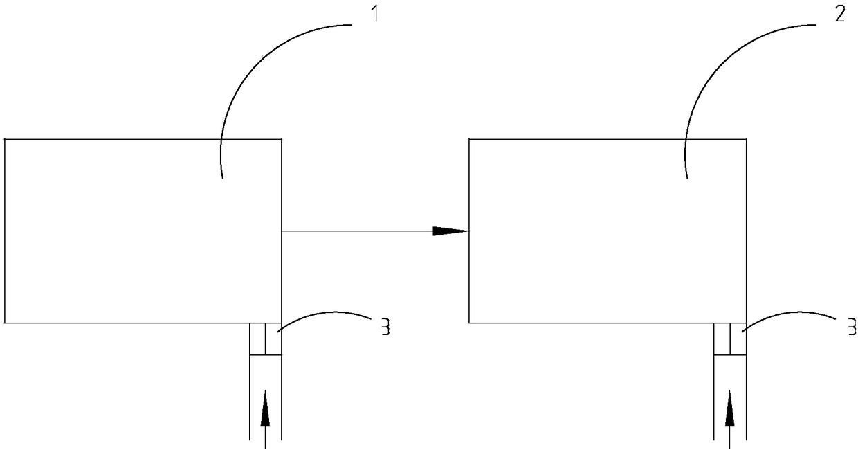
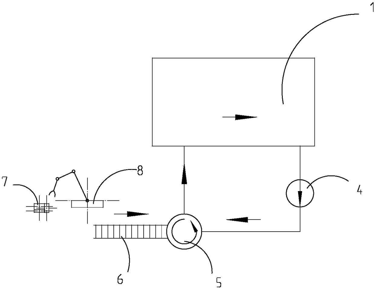
[0018] refer to Figure 1-Figure 2 . A kind of aluminum liquid refining equipment of the present invention, comprises smelting furnace 1 and holding furnace 2, and the bottom of smelting furnace 1 and holding furnace 2 is respectively provided with ventilating brick 3, refining gas enters melting furnace 1 and holding furnace 2 respectively through ventilating brick 3 The molten aluminum in the smelting furnace 1 and the holding furnace 2 is refined.

[0019] The upper part of the melting furnace 1 is provided with the feeding port of the melting furnace 1, and the u...


PUM


Abstract

The invention belongs to the technical field of metal refining equipment, and discloses aluminum liquid refining equipment. The aluminum liquid refining equipment comprises a smelting furnace and a heat preservation furnace. Ventilation bricks are arranged at the bottom of the smelting furnace and the bottom of the heat preservation furnace. Refining gas enters the smelting furnace and the heat preservation furnace through the ventilation bricks so as to refine aluminum liquid in the smelting furnace and the heat preservation furnace. A smelting furnace feeding port is formed in the upper portion of the smelting furnace, and a heat preservation furnace feeding port is formed in the upper portion of the heat preservation furnace. The ventilation bricks are arranged under the smelting furnace feeding port and the heat preservation furnace feeding port. Compared with the related technologies, through the structure improvement, the aluminum liquid refining equipment achieves the followingtechnical effects that the ventilation bricks are used for conveying the refining gas, bubbles are small, more uniformity and stability are achieved, aluminum liquid rolling cannot be caused, and burnout is greatly reduced; and an automatic charging-stirring-refining-temperature measuring structure is adopted, the rough operation manner is changed, feeding can be achieved without furnace door opening, and temperature losses are avoided.

Description

【Technical field】 [0001] The invention relates to the technical field of metal refining equipment, in particular to a liquid aluminum refining equipment. 【Background technique】 [0002] During the smelting process of molten aluminum, it is necessary to refine the molten aluminum, degas and remove slag to obtain relatively pure molten aluminum. In the related art, one solution is to directly use steel pipes to blow argon and nitrogen into the smelting furnace to refine the molten aluminum. The disadvantage of this scheme is that 1) the bubbles of argon and nitrogen blown out by the steel pipe are large, and they rise up and run away without being fully mixed with the aluminum liquid, and the refining effect on the aluminum liquid is poor; 2) the argon and nitrogen blown out by the steel pipe are harmful The impact force generated by the molten aluminum causes the surface of the molten aluminum to roll, resulting in burning of the molten aluminum; 3) This scheme requires manu...

Claims


Application Information

Patent Timeline
Patent Type & Authority Applications(China)
IPC IPC(8): C22B21/06C22B9/05
CPCC22B9/055C22B21/064
Inventor 唐新文
Owner SNTO TECH GRP
Why Eureka
Try Eureka