A liquid level control device

A liquid level control and lever technology, which is applied in the field of aluminum alloy casting, can solve the problems of increasing the supply gap, increasing the supply flow, and reducing the supply gap, etc.

Active Publication Date: 2018-03-20
SOUTHWEST ALUMINUM GRP
View PDF7 Cites 0 Cited by
  • Summary
  • Abstract
  • Description
  • Claims
  • Application Information

AI Technical Summary

Problems solved by technology

Use the buoyancy of the ship-shaped funnel given by the aluminum liquid in the crystallizer to control the opening and closing gap between the injection pipe and the ship-shaped funnel, so as to achieve a dynamic balance, so as to achieve the purpose of controlling the liquid level, but the ship-shaped funnel needs to be installed after the bottoming and slag breaking Then put it into the molten aluminum, which will cause the liquid surface to roll, destroy the oxide film formed on the surface of the molten aluminum, cause secondary pollution, and affect the quality of casting; another stopper connected to the liquid level detector through the actuator, When in use, the stopper rod hangs directly above the injection pipe. When the flow starts, as the liquid level in the crystallizer rises, the liquid level detector transmits the signal to the actuator, and the actuator drives the stopper rod down, and the stopper rod The gap between the stopper and the injection pipe decreases, and the supply flow rate decreases; when the liquid level in the crystallizer is lower than the rated height, the actuator acts, the stopper rod rises, and the supply flow gap between the stopper rod and the injection pipe increases. Large, the supply flow increases, so as to achieve the purpose of controlling the liquid level. Controlling the liquid level through the stopper rod will not cause the liquid surface to roll over, and will not damage the oxide film to cause secondary pollution. It is an ideal liquid level. Control device, but this device needs to use more expensive liquid level detectors, actuators and other equipment, the cost is high, and it needs to be maintained frequently

Method used


Image

  • A liquid level control device
  • A liquid level control device
  • A liquid level control device

Examples


Embodiment Construction

[0026] The invention provides a liquid level control device to achieve the purpose of reducing manufacturing and maintenance costs while ensuring the quality of aluminum alloy melting and casting.

[0027] The following will clearly and completely describe the technical solutions in the embodiments of the present invention with reference to the accompanying drawings in the embodiments of the present invention. Obviously, the described embodiments are only some, not all, embodiments of the present invention. Based on the embodiments of the present invention, all other embodiments obtained by persons of ordinary skill in the art without making creative efforts belong to the protection scope of the present invention.

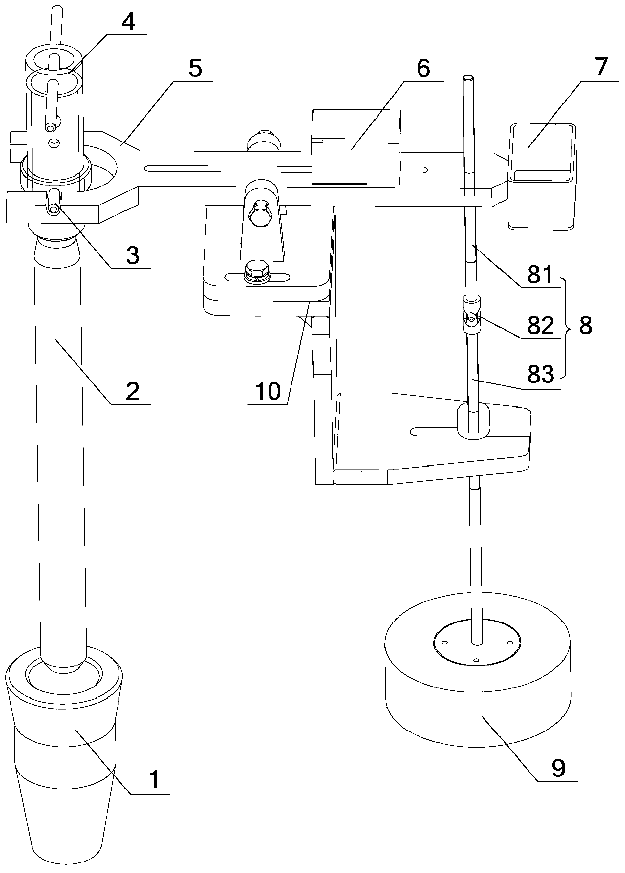
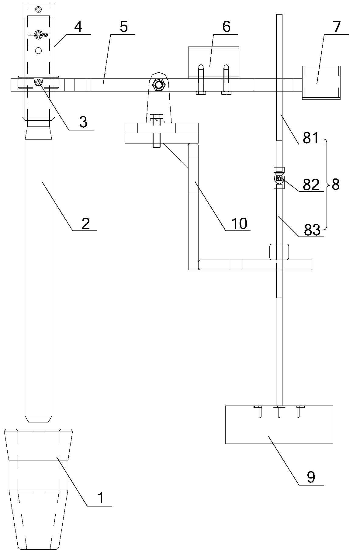
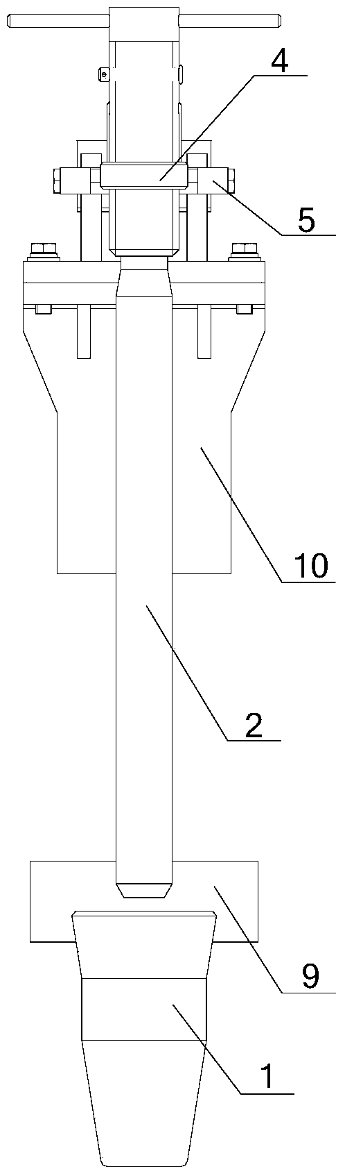
[0028] see Figure 1-Figure 4 , figure 1 A schematic diagram of the three-dimensional structure of the liquid level control device provided by the embodiment of the present invention; figure 2 The front view of the liquid level control device provided by the emb...


PUM


Abstract

The invention discloses a liquid level control device which comprises a rack, a lever, a stopper rod and a buoy, wherein the lever is arranged on the rack in a pivoting manner; the stopper rod is arranged at a first end of the lever; the buoy is arranged at a second end of the lever; one end of the stopper rod is movably connected with the lever, so as to allow the stopper rod to be vertically hung above a lower injection pipe all the time; the buoy and the stopper rod are positioned at the same side of the lever; the buoy is connected with the lever through a buoy connecting rod. The buoy at the second end of the lever rises and falls along with the liquid level, and the stopper rod at the first end of the lever moves opposite to the buoy; if the liquid level rises, the stopper rod falls, and a gap between the stopper rod and the lower injection pipe is narrowed, if the liquid level falls, the stopper rod rises, and the gap between the stopper rod and the lower injection pipe is enlarged, so that the increase and decrease of a flow rate are controlled automatically according to the rising and falling of the liquid level in a crystallizer, dynamic equilibrium of the liquid level in the crystallizer is realized, and the liquid level is kept within a reasonable range; no liquid level tumble can be caused; the introduction of secondary pollution is avoided; and a pure mechanical structure is adopted, so that the liquid level control device is simple in structure, and low in manufacturing cost and maintenance cost.

Description

technical field [0001] The invention relates to the technical field of aluminum alloy melting and casting, in particular to a liquid level control device. Background technique [0002] In the production of aluminum alloy casting, in order to ensure the smooth formation of ingots and improve the metallurgical quality, we need to control the flow of the flow plate and the liquid level of the aluminum liquid in the crystallizer to make it reach a relatively stable state. [0003] In the prior art, there are mainly two types of devices for controlling the flow rate of the flow plate and the liquid level in the crystallizer: one is a boat-shaped funnel, and when in use, put the boat-shaped funnel into the aluminum liquid and place it under the injection pipe. Use the buoyancy of the ship-shaped funnel given by the aluminum liquid in the crystallizer to control the opening and closing gap between the injection pipe and the ship-shaped funnel, so as to achieve a dynamic balance, so...

Claims


Application Information

Patent Timeline
Patent Type & Authority Patents(China)
IPC IPC(8): B22D11/18
CPCB22D11/181
Inventor 张桂上
Owner SOUTHWEST ALUMINUM GRP
Why Eureka
Try Eureka