Bench-work pin puller

A technology of pin puller and fitter, which is applied in the manufacture of tools and hand-held tools, etc. It can solve the problems of poor cushioning capacity of the convex handle, hand vibration, and inconvenient use, and achieves the effects of high safety, reduced use cost, and comfortable use

Pending Publication Date: 2019-03-08
GUANG DONG XING LIAN PRECISE MACHINERY
View PDF0 Cites 0 Cited by
  • Summary
  • Abstract
  • Description
  • Claims
  • Application Information

AI Technical Summary

Problems solved by technology

[0003] (1) The design of the sleeve rod of the existing pin puller is flawed. It is generally a cylindrical structure. During work, when the sleeve rod slides up and down and hits the convex handle at the end of the pull rod, the hand will be pinched, and the buffer of the convex handle The ability is very poor, and the

Method used


Image

  • Bench-work pin puller
  • Bench-work pin puller
  • Bench-work pin puller

Examples


Embodiment

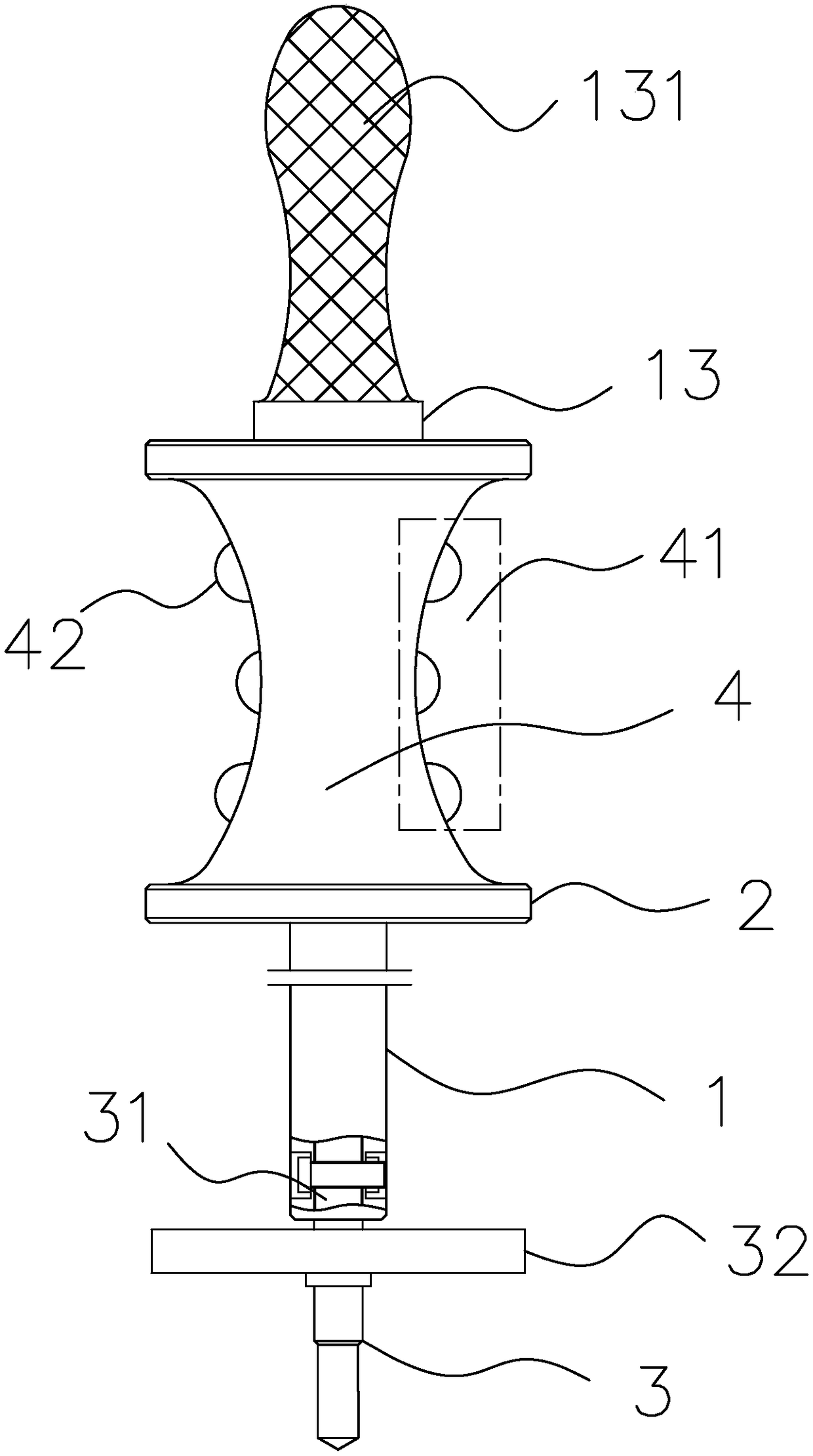
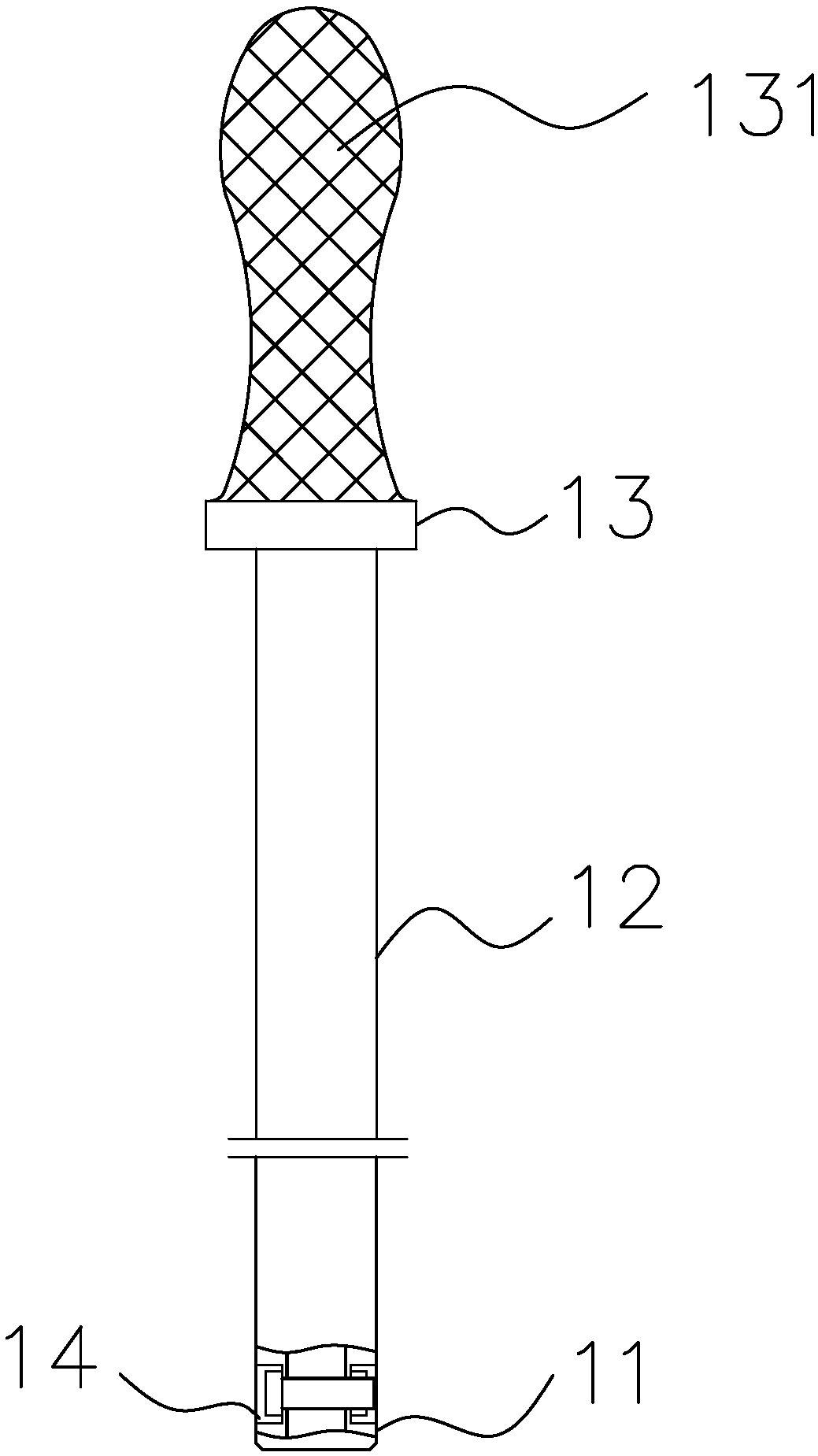
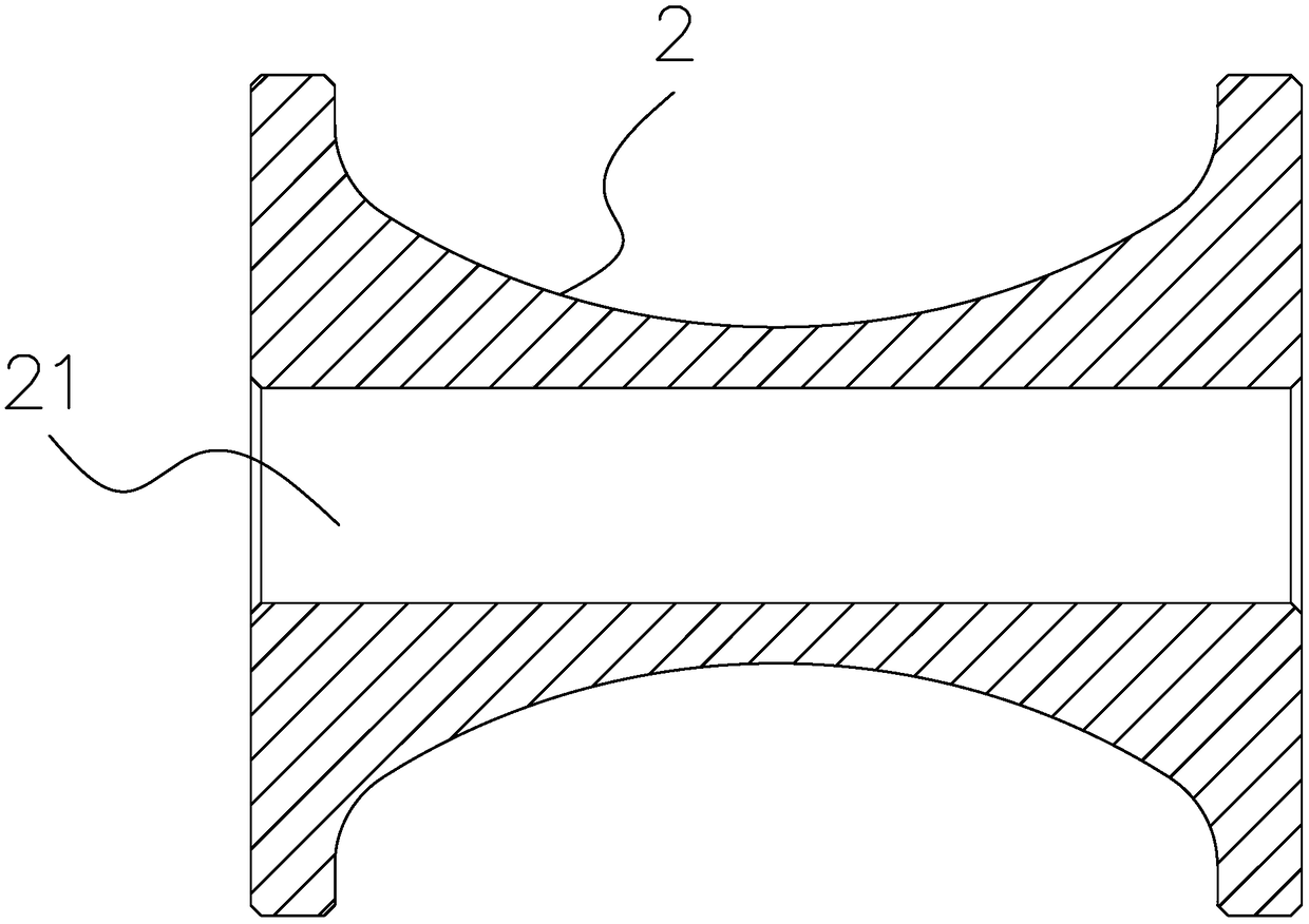
[0024] This embodiment discloses a fitter's pin puller, which includes a pull rod 1, a sleeve rod 2, and a pulling head 3. The sleeve rod 2 is sleeved on the pull rod 1, and the pull head 3 is installed at the end of the pull rod 1. The pull rod 1 includes, from bottom to top, a connecting end 11 for connecting with the pulling head 3, a straight rod 12 for socketing the sleeve rod 2, and a lug 13 for impacting and pulling the pin with the sleeve rod 2. The lug The diameter of 13 is greater than the diameter of the straight rod 12. The sleeve rod 2 is a single-leaf hyperboloid structure. The central axis of the sleeve rod 2 is provided with a through hole 21 for being sleeved on the pull rod 1. The diameter is larger than the diameter of the straight rod 12. One end of the pulling head 3 is provided with a connection position 31 connected to the connecting end 11, and the other end of the pulling head 3 is provided with a thread for connecting with a pin. The pulling head 3 an...


PUM

PropertyMeasurementUnit
Lengthaaaaaaaaaa
Diameteraaaaaaaaaa

Abstract

The invention discloses a bench-work pin puller. The bench-work pin puller comprises a pull rod, a sleeve rod and a pull head, the sleeve rod is connected on the pull rod in a sleeving mode, the pullhead is installed at the end of the pull rod, wherein the pull rod sequentially comprises a connecting end used for being connected with the pull head, a straight rod used for being connected with thesleeve rod in a sleeved mode and a convex handle used for impacting with the sleeve rod for pin pulling from bottom to top, the diameter of the convex handle is larger than that of the straight rod,the sleeve rod is of a one-sheeted hyperboloid structure, a through hole used for being connected on the pull rod in a sleeving mode is formed in the central axis of the sleeve rod, the diameter of the through hole is larger than that of the straight rod, and a connecting position which is connected with the connecting end is arranged at one end of the pull head, and the other end of the pull headis provided with a thread used for being connected with a pin piece.

Description

technical field [0001] The invention belongs to the technical field of mold maintenance, and in particular relates to a fitter pin puller. Background technique [0002] In the technical field of mold maintenance, it is often necessary to pull out the inserts or fixing pins on the formwork. However, since the inserts and fixing pins generally have an interference fit with the mold, it is difficult to disassemble and pull out directly. The pin puller, the pin puller commonly used in the market, has defects of varying degrees, such as: [0003] (1) The design of the sleeve rod of the existing pin puller is flawed. It is generally a cylindrical structure. During work, when the sleeve rod slides up and down and hits the convex handle at the end of the pull rod, the hand will be pinched, and the buffer of the convex handle The ability is very poor, and the hand will vibrate when a little force is applied, which is extremely inconvenient to use; [0004] (2) The puller head of th...

Claims


Application Information

Patent Timeline
IPC IPC(8): B25B27/02
CPCB25B27/02
Inventor 姜晓平卢佳魏以宏
Owner GUANG DONG XING LIAN PRECISE MACHINERY
Why Eureka
Try Eureka