
Floor type burner regulating device and using method
An adjustment device and floor-standing technology, which is applied in the direction of furnaces, lighting and heating equipment, furnace types, etc., can solve the problems of inconvenient installation, adjustment and maintenance, high labor intensity of workers, and complicated settings, so as to reach in or out of the burner Smooth and unobstructed, compact structure and layout, wide application effect
- Summary
- Abstract
- Description
- Claims
- Application Information
AI Technical Summary
Problems solved by technology
Method used
Image

Examples
Embodiment Construction
[0029] The specific embodiment of the present invention will be further described below in conjunction with accompanying drawing:
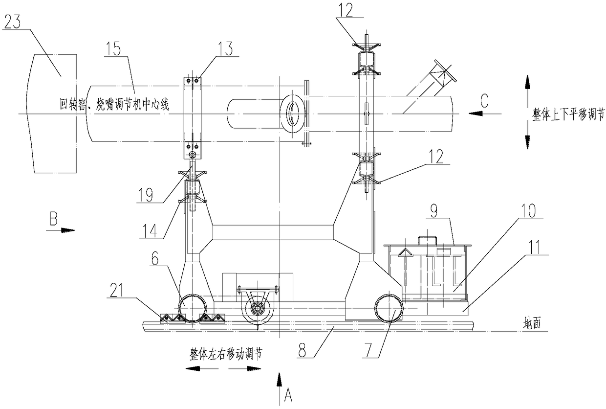
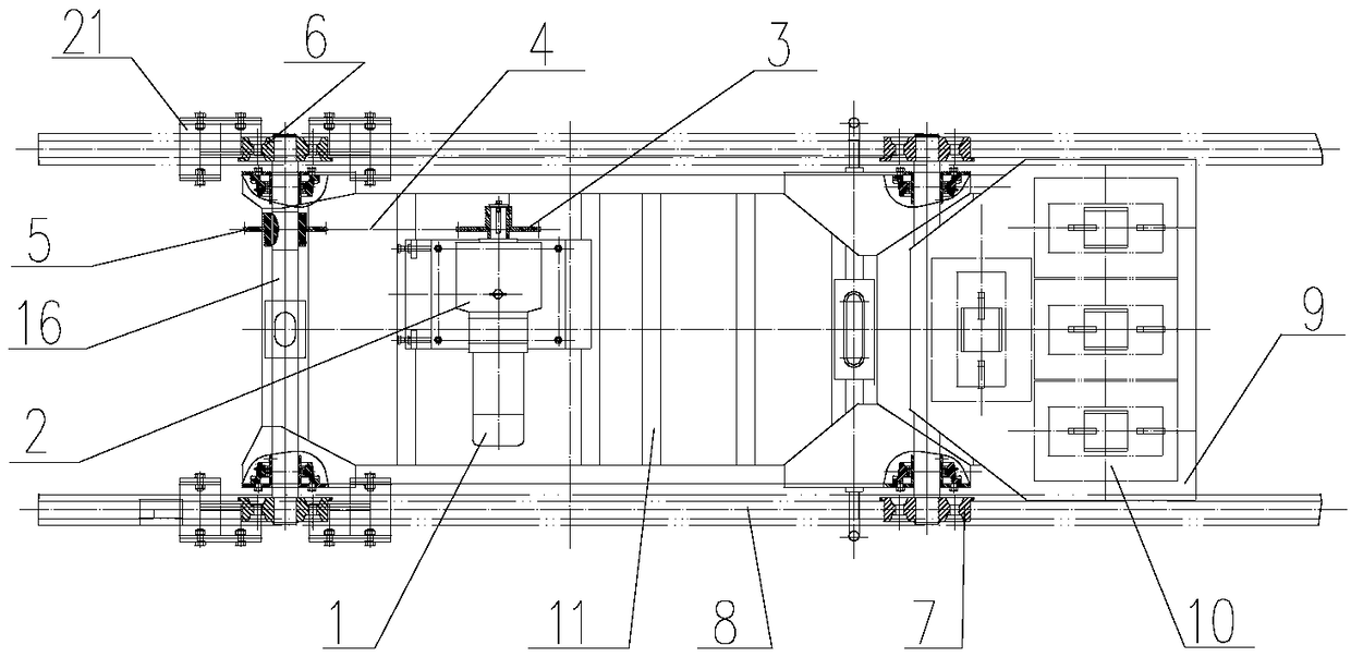
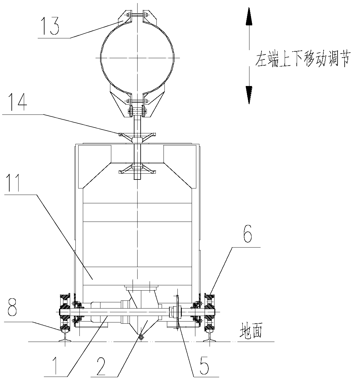
[0030] See Figure 1 ~ Figure 4 As shown, a floor-type burner adjustment device related to the present invention includes a driving traveling device, a support 11 and an adjusting device, and the driving traveling device is composed of a driving motor 1, a reducer 2, a sprocket (one) 3, a sprocket (2) 5, roller chain 4, front wheel 6, front axle 16, rear wheel 7, rear axle and track 8 are formed, wherein drive motor 1, speed reducer 2 are arranged on the support 11, and the input shaft of speed reducer 2 and The drive motor 1 is connected, the output shaft is connected with the sprocket (one) 3, and the sprocket (one) 3 is connected with the sprocket (two) 5 arranged on the front axle 16 through the roller chain 4, and the front axle 16 and the rear axle are both Be fixed on the bracket 11 by bolts on the bearing with seat, the two ends of the fr...
PUM
 Abstract
Description
Claims
Application Information